IDS X-Series Training v2.7
8.4. IDS X-Series Output Expander module
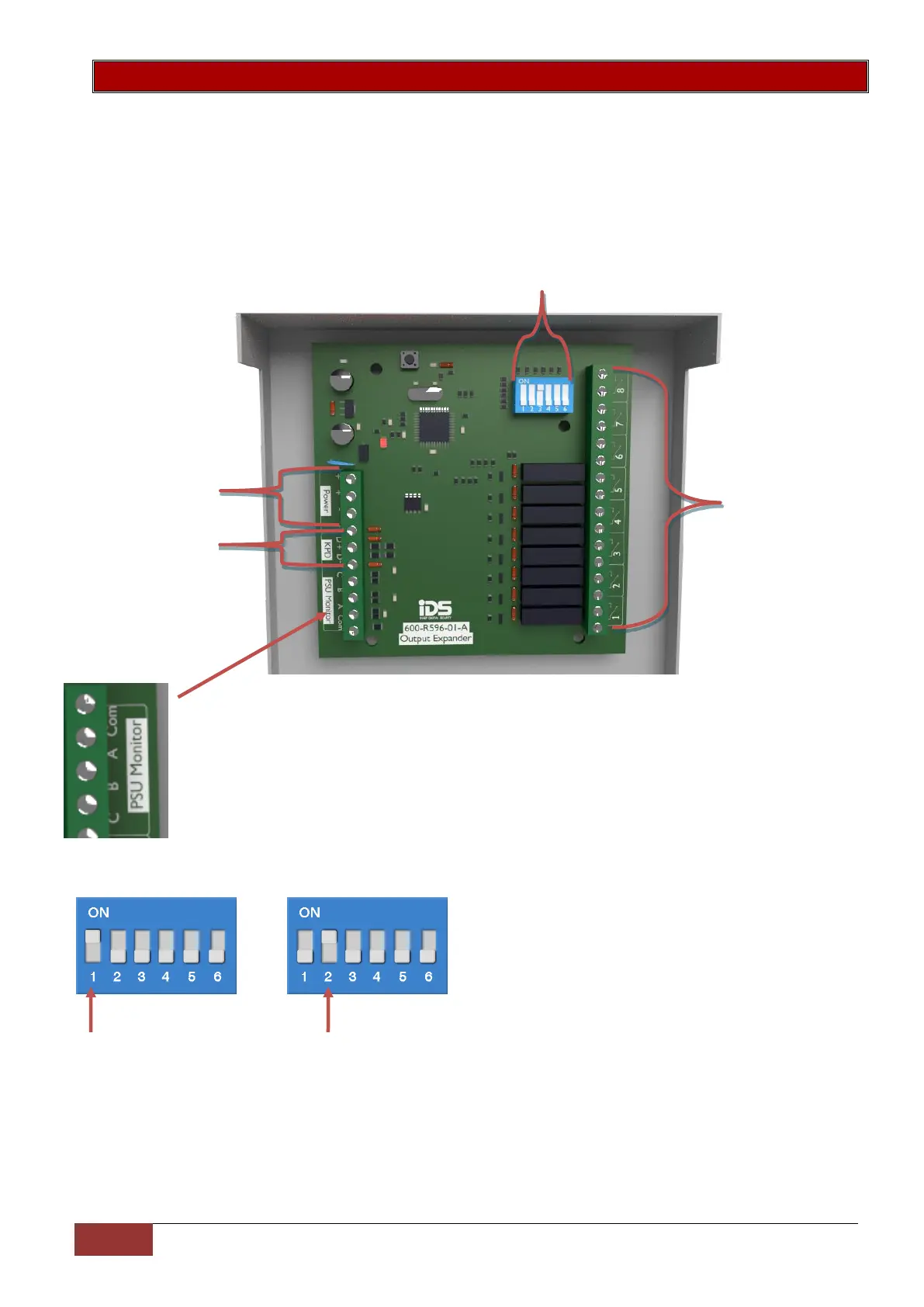
The IDS X-Series alarm panels support two PGM Output Expander Modules. Each Output Expander has
eight programmable normally open relay outputs.
The outputs are programmed by addresses and actions from a defined list of programmable output
events, which will be covered in the programming section of this manual.
The connector labelled A, B, C and Com connect to the corresponding connectors with the
same label on the Monitored Power Supply.
A – Mains Failure monitoring
B – Low Battery monitoring
C – Fuse Failure monitoring
Com – Common
X-Series Output Expander ID and corresponding output addresses:
Output Expander ID1 Output Expander ID2
Outputs 18 - 25 Outputs 26 - 33
Each output is a
normally open 1amp
rated relay
12v DC power supply,
same power source as
keypad bus
X-Series Keypad
bus connections
The Dipswitches are used to set the output expanders ID
 Loading...