IDS X-Series Training v2.7 | Hardware
7. Onboard Expander Connection
The number of zones on the X64 and X16 alarm panels can be expanded via zone expanders. Zones 9 to
16 are added by plugging the onboard expander (or plug-in expander) onto the PCB via this connector.
Not available on the X8s.
8 pin connect Standoff mounting hole
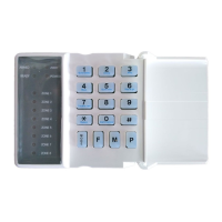
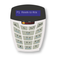
8. Keypad Bus
All devices connected to the bus should be connected in a daisy chain formation (one after each other) for
the best results, though the X-Series Panel does not need to be in the beginning or end of the daisy chain.
Note: All X-Series keypad bus devices must be powered from the X-Series panel unless an IDS RS485 Bus
Isolator is used, as described in point 8.6.
8.1. IDS X64 – Wired 8 Zone Expander Module
NOTE: Zone 9 - 16 are reserved for the onboard plug-in expander and cannot be allocated to the
wired bus expander zones, even if the onboard expander is not used.
Zones – End of Line Supervised
Tamper – Connects directly to a tamper
switch
12V – Connect to keypad bus
D+ D- – Connect to keypad bus
Dipswitch – ID the expander using
binary as shown below
 Loading...