IDS X-Series Training v2.7
10. X-Series aXess
X-Series v2.6x and higher supports an integrated access control system with up to eight doors.
Each door reader can be configured as an access reader, arm/disarm reader or both. Each door is
controlled by either a reader interface, which can support two readers, or a single integrated reader, both
with a push to release button, and a door status input.
All aXess programming can be done from an X-Series LCD Keypad and will be explained in the
programming section of this manual.
In this manual when using the word “door” we are referring to the aXess interface and reader as one
system, which may or may not be connected to a physical door as with an arming only door.
10.1. Interface
The interface is the “brain” of the X-Series aXess control system, all tag information and door permissions
are stored on each interface and therefore does not need to communicate with the X-Series panel to
grant/deny access permissions, this allows readers to continue working in the offline mode, although not
enabled by default.
An interface is required for each access door reader or each arming reader to a maximum of eight
interfaces/doors and is wired to the X-Series Panel RS485 keypad bus.
Note: Only use ‘Remove Missing Devices’ (0*4* in installer programming) if the aXess Interface is being
permanently removed. If the device has just lost communications and reconnects then you will need to
default the aXess Interface before it registers on the panel and this loses all tags. Use IDSwift2 to
download all tag information before replacing any interfaces or removing missing devices.
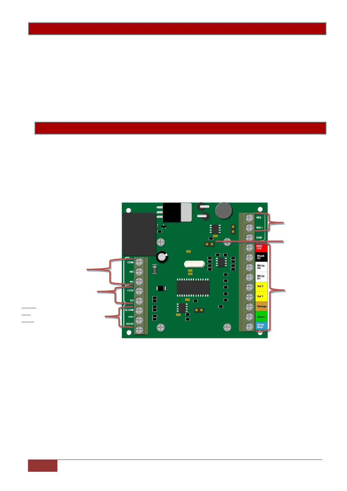
X-Series keypad
bus connections
Relay output for door trigger.
Supports both Normally
Open (NO) and Normally
Closed (NC) devices
External inputs;
Alarm is for the Interface tamper
Exit is used for a Push to exit button
Door is used for the door switch.
These are NC inputs and wired to
the interface 0V
Mode Jumper: Short
for weigand devices
 Loading...