Do you have a question about the IEI Technology ICE-BT-T6 and is the answer not in the manual?
| Form Factor | Mini-ITX |
|---|---|
| Max Memory | 32 GB |
| Storage Interface | SATA 6Gb/s |
| CPU | Intel Core i7/i5/i3, Celeron |
| Memory Slots | 2 x DDR4 SO-DIMM |
| Memory Speed | DDR4 2133 MHz |
| M.2 | 1 x M.2 M-key |
| USB Ports | 2 x USB 2.0 |
| Display Output | 1 x HDMI |
| Audio | Realtek ALC888S |
| Operating Temperature | 0°C ~ 60°C |
| SATA | 2 x SATA 6Gb/s |
General introduction to the ICE-BT-T6 COM Express Type 6 module and its design.
Lists different model variations of the ICE-BT-T6 with their respective specifications.
Highlights the main features and capabilities of the ICE-BT-T6 COM Express module.
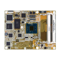
Illustrates the on-board components and connectors of the ICE-BT-T6 module.
Provides the physical dimensions of the ICE-BT-T6 COM Express module in millimeters.
Explains the data flow between system components like chipset and CPU.
Lists detailed technical specifications, including form factor, SoC, memory, and interfaces.
Essential safety measures to prevent electrostatic discharge (ESD) damage.
Guidelines for safely unpacking the ICE-BT-T6 COM Express module.
Lists the specific components included with the ICE-BT-T6 COM Express module.
Lists optional components that may be purchased separately for the ICE-BT-T6.
Overview of the main peripheral interface connectors on the module.
Visual representation of connector locations on the ICE-BT-T6 front and solder sides.
Lists and categorizes the peripheral interface connectors on the ICE-BT-T6.
Details the internal connectors found on the ICE-BT-T6 module.
Pinout and location details for the COM Express Connector AB (J1) on the ICE-BT-T6.
Pinout and location details for the COM Express Connector CD (J2) on the ICE-BT-T6.
Information regarding the DDR3 SO-DIMM connectors for memory installation.
Critical safety measures to prevent ESD damage during installation.
Important notices and considerations before proceeding with the installation.
Step-by-step instructions for installing SO-DIMM memory modules onto the board.
Details jumper settings, including LVDS panel type selection via DIP switch.
Instructions for physically mounting the ICE-BT-T6 module onto a baseboard.
Covers accessing, navigating, and basic operations of the BIOS setup.
Explains system information in the Main menu and advanced configurations.
Details BIOS settings for ACPI, IO, CPU, Thermal, IDE, Security, and Boot.
Covers North Bridge and South Bridge settings, including graphics and audio.
Manages system security, passwords, and boot device configurations.
Options for saving changes, restoring defaults, and exiting the BIOS setup.
Lists the types of drivers available for installation on the system.
Steps to launch the driver installation program from the provided CD.
Detailed guide for installing the Intel chipset drivers.
Step-by-step instructions for installing the Intel graphics drivers.
Guide for installing the LAN drivers for network connectivity.
Advanced Configuration and Power Interface (ACPI) for power management.
Basic Input/Output System (BIOS) firmware for hardware initialization during boot.
Standard for modular computing, defining form factor and connectors.
Double Data Rate 3 (DDR3) SDRAM memory with improved performance.
Serial ATA (SATA) interface for connecting storage devices like hard drives.
Universal Serial Bus (USB) standard for connecting peripheral devices.
Introduction to the digital I/O connector, GPIO, and BIOS interrupt control.
Assembly language code example for digital I/O input configuration.
Assembly language code example for digital I/O output configuration.
Table detailing hazardous substances presence and China RoHS compliance.


