ICE-BT-T6 COM Express Module
Page 32
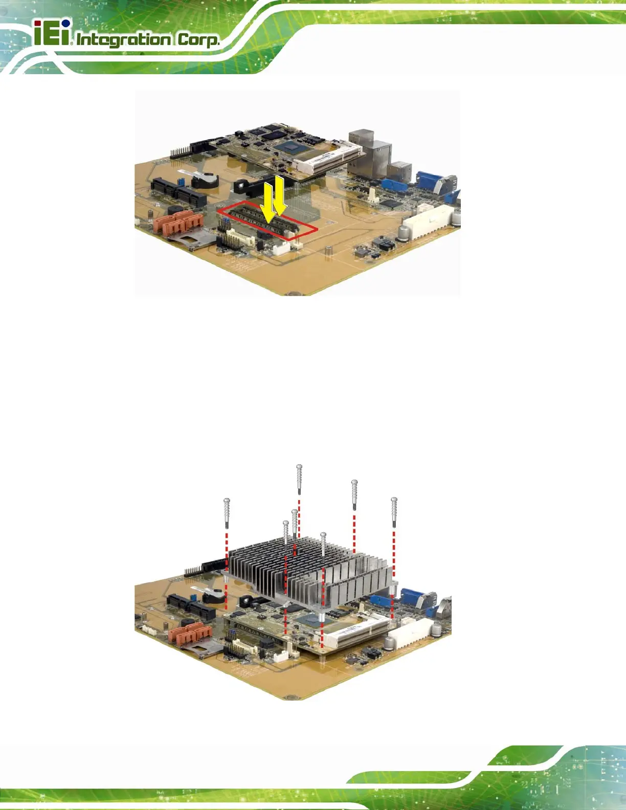
Figure 4-3: Connect the COM Express Connectors
Step 2: Ensure a thermal pad is placed on the CPU of the ICE-BT-T6.
Step 3: Place the heatsink on the ICE-BT-T6, aligning the retention screw holes
(Figure 4-4).
Step 4: Secu
re the heatsink to the ICE-BT-T6 and the baseboard with the supplied
retention screws (Figure 4-4).
Figure 4-4: Secure the Heatsink
 Loading...


