ICE-BT-T6 COM Express Module
Page 24
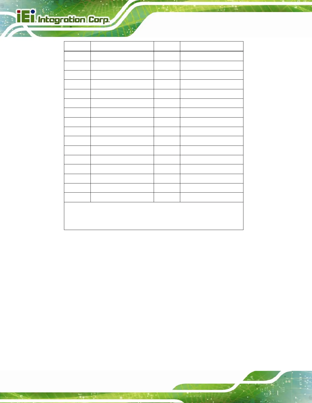
Pin No. Description Pin No. Description
C95
RSVD
D95
RSVD
C96
GND12
D96
GND33
C97
RSVD6
D97
RSVD
C98
RSVD
D98
RSVD
C99
RSVD
D99
RSVD
C100
GND13
D100
GND25
C101
RSVD
D101
RSVD
C102
RSVD
D102
RSVD
C103
GND
D103
GND34
C104
VCC_12V1
D104
VCC_12V7
C105
VCC_12V2
D105
VCC_12V8
C106
VCC_12V3
D106
VCC_12V9
C107
VCC_12V4
D107
VCC_12V10
C108
VCC_12V5
D108
VCC_12V11
C109
VCC_12V6
D109
VCC_12V12
C110
GND14
D110
GND26
* DDI 1 signals (D15, D16, D26, D27, D29, D30 D32, D33, D34, D36 and D37) are
only available upon special order request. These pins are reserved on the standard
ICE-BT-T6 module.
Table 3-3: COM Express Connector CD Pin Definitions
3.2.3 SO-DIMM Connectors
CN Label: DIMM1, DIMM2
CN Type:
204-pin DDR3 SO-DIMM connector
CN Location:
See Figure 3-5
The SO-DIM
M connectors are for installing DDR3L memory on the system.
 Loading...


