14
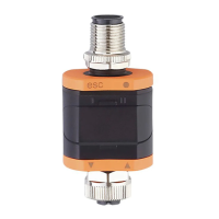
To ensure the protection rating fully tighten the screws of the used M12
connectors� Protection rating (→ 11 Technical data)�
6.1 Maximum length of the connection cables
Without IO-Link on either side: 30 m�
With IO-link communication on the master side: 20 m�
All cables must be provided with a strain relief min� 200 mm behind the
connectors�
7 Operation
After power on, the device is in the operating mode (SIO)� It carries out its
measurement and evaluation functions and provides output signals according to
the set parameters (→ 8 Parameters)�
7.1 Functions output 1
OUT1 (connector, pin 4):
• Digital output (status according to the set switching function)
• IO-Link interface
Selectable switching functions:
• Hysteresis functions, normally open / normally closed (→ 8.3.1)
• Window functions, normally open / normally closed (→ 8.3.2)
OUT1 changes its status if the input signal is above or below the set switching
limits� First the set point SP1 is set, then the reset point rP1 (→ 8.3.1)�
The hysteresis defined remains even if SP1 is changed again� Changing
the parameter rP1 also changes the hysteresis�
The width of the window can be set by means of the difference between FH1/FL1�
FH1 = upper value
FL1 = lower value
7.2 Functions output 2
OUT2 (connector, pin 2):
• Analogue output (looping through the analogue input signal)�