7
UK
3 Functions and features
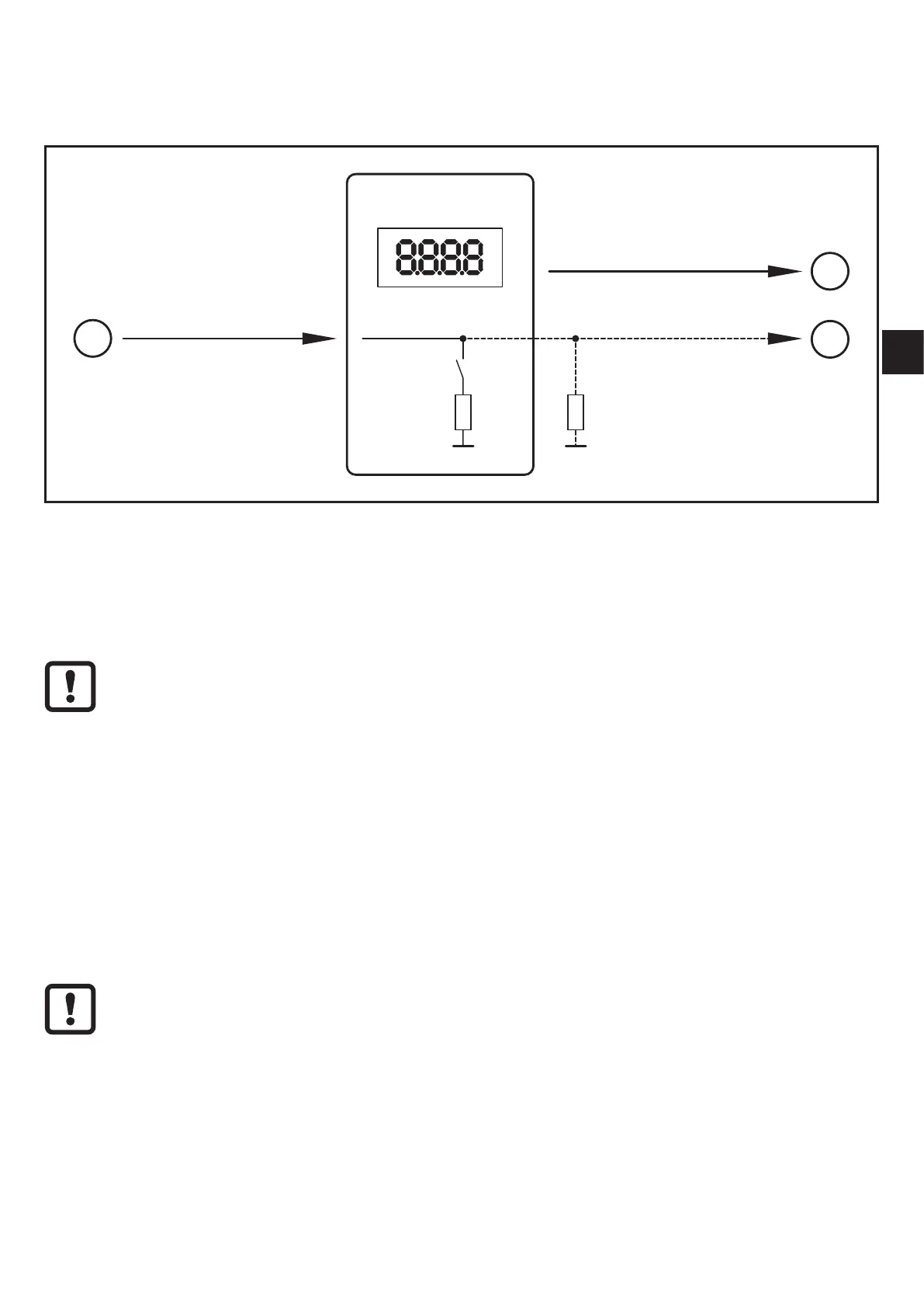
3.1 Block diagram
1
Input (analogue) I
IN
OUT2 (analogue)
2
OUT1 (digital)
3
DP2200
A�trm
*) **)
Inputs/outputs of the device
1: IN (analogue input I
IN
)
2: OUT1 (digital output)
3: OUT2 (analogue output I
OUT
= I
IN
)
A�trm = analogue termination OUT2
*) switchable internal load
**) external load (optional)
The current loop of the analogue input must be terminated� Only one load
may be connected, either an internal or an external load�
(→ 8.4.2 A.trm ─ analogue termination for OUT2)
(→ 12 Fault correction)
3.2 General application and functionality
The device is used for the evaluation of an analogue signal (4���20 mA) from a
connected sensor or another device with analogue output (4���20 mA)� The device
has one analogue current input and two outputs: output 1 (digital) and optionally
output 2 (analogue current output)�
The device is intended for indoor use only�
Observe the operating conditions (→ 11 Technical data)�
There are basically two modes in which the device can be operated:
• As stand-alone device
The device compares the measured current value with the set parameters and
switches its output according to the selected parameters� This mode is without
IO-Link functionality� The parameters can, however, also be set with an IO-Link
tool�