3
UK
6�4�2 Installation in closed metal tanks (with flange plate) ��������������������������22
6�4�3 Installation in open tanks ��������������������������������������������������������������������23
6�4�4 Installation in plastic tanks ������������������������������������������������������������������ 24
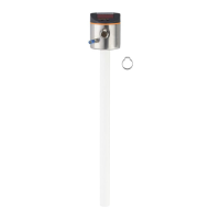
6�5 Installation of the unit with coaxial probe in the tank �����������������������������������24
6�6 Alignment of the sensor housing �����������������������������������������������������������������25
7 Electrical connection ������������������������������������������������������������������������������������������25
8 Operating and display elements ������������������������������������������������������������������������26
9 Menu ������������������������������������������������������������������������������������������������������������������27
9�1 Menu structure ���������������������������������������������������������������������������������������������27
9�2 Explanation of the menu ������������������������������������������������������������������������������ 28
10 Parameter setting ��������������������������������������������������������������������������������������������29
10�1 Parameter setting in general ���������������������������������������������������������������������29
10�2 Basic settings (unit on delivery) ����������������������������������������������������������������� 31
10�2�1 Entering the probe length �����������������������������������������������������������������31
10�2�2 Setting to the medium �����������������������������������������������������������������������31
10�2�3 Entering the type of probe used �������������������������������������������������������31
10�3 Configuration of the display �����������������������������������������������������������������������32
10�4 Offset setting ����������������������������������������������������������������������������������������������32
10�5 Setting of output signals ����������������������������������������������������������������������������32
10�5�1 Setting of the output function for OUT 1 �������������������������������������������32
10�5�2 Set the switching limits (hysteresis function) ������������������������������������32
10�5�3 Set the switching limits (window function) ����������������������������������������32
10�5�4 Setting of the switch-off delay for OUT1 ������������������������������������������� 33
10�5�5 Setting of the output function for OUT2 (analogue output) ���������������33
10�5�6 Scale the analogue signal ����������������������������������������������������������������33
10�5�7 Response of the outputs in case of a fault ���������������������������������������33
10�5�8 Setting of the delay time after signal loss �����������������������������������������33
10�6 Reset all parameters to factory setting ������������������������������������������������������34
10�7 Changing basic settings ����������������������������������������������������������������������������34
10�7�1 Re-enter the probe length �����������������������������������������������������������������34
10�7�2 Setting to another medium ���������������������������������������������������������������34
10�7�3 New entering of the type of probe used ��������������������������������������������34
11 Operation ���������������������������������������������������������������������������������������������������������35
11�1 Operating indicators ����������������������������������������������������������������������������������35
11�2 Read the set parameters ���������������������������������������������������������������������������35