28
Configuration of the display10.3
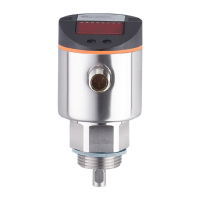
Select [Uni] and set the unit of measurement: [cm], [inch]� ►
Factory setting: cm�
Select [SELd] and set type of indication: ►
[L] = The level is indicated in cm or inch� -
[L%] = The level is indicated in percent of the final value of the measur- -
ing range�
[OFF] = The display is switched off in the operating mode� When one -
of the buttons is pressed the current measured value is displayed for
15 s� The LEDs remain active even if the display is deactivated�
Offset setting10.4
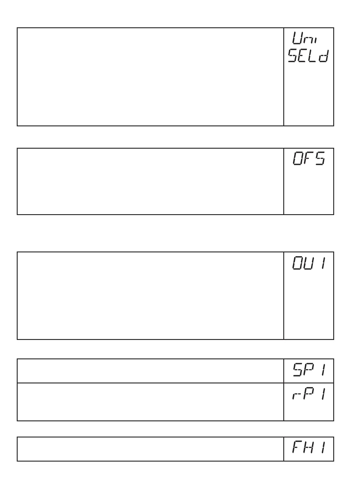
Select [OFS] and enter the distance between bottom of the tank and ►
lower edge of the probe�
Afterwards, display and switch points refer to the real level� Factory setting:
[OFS] = 0�
Note: Set [OFS] before setting the switching limits (SPx, rPx)� Otherwise,
the switching limits shift by the value of the set offset�
Setting of output signals10.5
Setting of the output function for OUT110.5.1
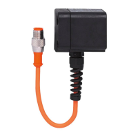
Select [OU1] and set the switching function: ►
[Hno] = hysteresis function/NO,
[Hnc] = hysteresis function/NC,
[Fno] = window function/NO,
[Fnc] = window function/NC�
Note: If the upper switch point is used as an overflow protection, the setting
OU1 = Hnc (NC function) is recommended� The principle of normally closed
operation ensures that wire break or cable break is also detected�
Setting of switching limits (hysteresis function)10.5.2
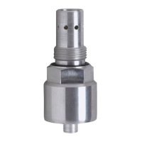
Make sure that the function [Hno] or [Hnc] is set for [OU1]� ►
Select [SP1] and set the value at which the output switches� ►
Select [rP1] and set the value at which the output switches off� ►
rP1 is always smaller than SP1� The unit only accepts values which are
lower than the value for SP1�
Setting of switching limits (window function)10.5.3
Make sure that the function [Fno] or [Fnc] is set for [OU1]� ►
Select [FH1] and set the upper limit of the acceptable range� ►