12
5.2 Installation process
The unit is installed by means of an adapter:
► Ensure cleanliness of the sealing areas� Remove protective packaging only
just before mounting� In case of damaged sealing areas replace the unit or the
adapter�
5.2.1 Installation LMT1x0, LMT1x1 and LMT1x2
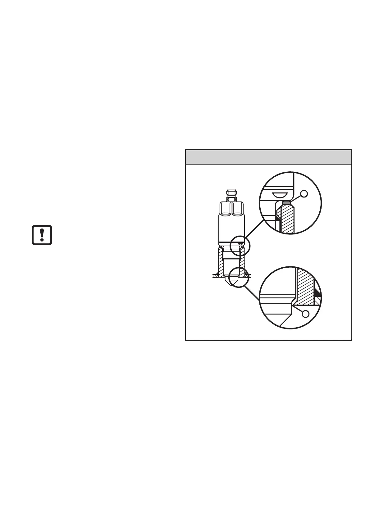
► Slide the supplied seal (black O-ring), (1), fig� 6-2, over the thread onto the
sensor and/or check for correct position�
It seals the gap on the back between the sensor and the adapter�
If a seal is supplied with the sensor,
please use this seal� If no seal is
supplied with the sensor, use the
seal supplied with the adapter�
O-ring too large: Leakage on the
sensor tip (2), fig� 6-2�
O-ring too flat: Leakage on the gap
on the back between the sensor and
the adapter�
Fig. 6-2
1
2
1: Seal on the back (O-ring, black)
2: Sealing cone / sealing PEEK on metal
► Slightly grease the thread of the sensor using a lubricating paste which is
suitable and approved for the application�
► Screw the sensor into the respective process connection and tighten it�
Max� tightening torque: 20…25 Nm
► After installation check the tank / pipe for ingress resistance�
Unsuitable seals may cause
problems with ingress
resistance: