27
4-6. Adjustment Procedure
Adjustments (1) thru (4) can be made more precisely by getting the space around the monitor as dark as possible.
REFERENCE : 6500K
FILE 1 : 6500K
FILE 2 : 9300K
FILE 3 : 6500K
* The white balance can be adjusted using an ana-
lyzer or the optional ASP-80 for automatic adjust-
ment.
* Use the FILE 3 when you want to store custom-
adjusted color temperature data.
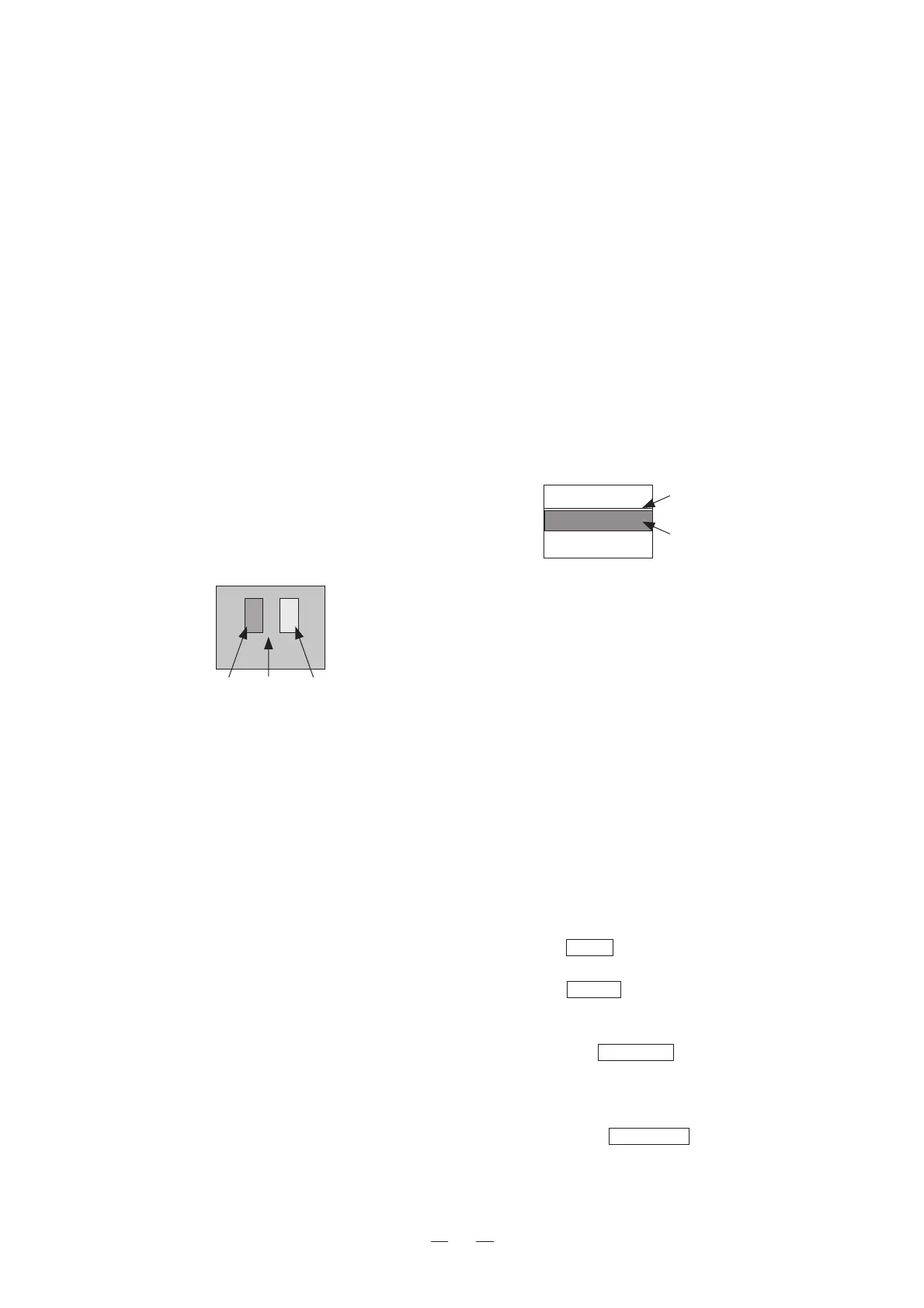
b) Precautions
To stabilize the black level over a long period of
time, this monitor adopts the beam feedback clamp
method which detects beam currents to perform
clamping. Therefore one line (Part A in Fig. 4-6-
2) is displayed on the CRT.
If the BACKGROUND is lowered so that Part B in
Fig. 4-6-2 becomes invisible, the line at Part A dis-
appears, disabling the detection of the beam cur-
rent.
Pay careful attention when adjusting BACK-
GROUND.
c) Adjustment procedure 1 (Adjusting visually)
①Input signal
Input a color bar signal or select the internal TEST
signal (gray scale with pluge).
② Setting the file
Select the file whose white balance you want to
change.
Adjust BRIGHTNESS and CONTRAST properly
before adjusting the white balance.
③ Settings before adjusting BACKGROUND
Set the MONO switch on the front panel to ON for
color bar signals and set the black/white screen.
Set the SET UP switch in the drawer panel to ON
and set as follows.
④Initial adjustment of low light
Set only the R.SCREEN switch to ON (red screen
only), adjust the R.BACKGROUND data so that
the red line at Part B in the Fig. 4-6-2 illuminates
slightly.
Set only the G.SCREEN switch to ON (green
screen only), adjust the G.BACKGROUND data so
that the green line at Part B in the Fig. 4-6-2 illu-
minates slightly.
PartA
-2%
PartC
+2%
PartB
0%
Fig. 4-6-1. Pluge Portion
PartA
Beamfeedbackline
PartB
SETUPlineforreduced
verticaldeflection
Fig. 4-6-2. SETUP ON State
(1)Adjusting the brightness
a) Brightness
Brightness adjustment is to set the appropriate
black level.
It must be adjusted according to the brightness of
the environment in which the monitor is used so
that the black level is not too high or too low.
b) Adjustment procedure
① Input signal
Select the gray scale with pluge using the internal
TEST signal.
② Adjusting BRIGHTNESS
While taking note of the pluge portion at the cen-
ter of the signal, decrease BRIGHTNESS gradu-
ally until the brightness of Part A (–2%) and Part
B (0%) in the figure cannot be visually differenti-
ated.
Also check that Part C (+2%) is illuminated slightly.
If this cannot be confirmed, raise BRIGHTNESS
until Part C illuminates slightly.
(2)Adjusting the contrast
a) Contrast
Contrast of the monitor is factory-adjusted to the
level optimum for monitoring images.
b) Precautions
Leaving the monitor in the bright state (where the
OVER LOAD LED is lit) for a long period of time
will shorten the life of the CRT. Therefore adjust
the PRESET data to the value shown below.
c) Adjustment procedure
① Input signal
Input a window signal (100%) or select the inter-
nal TEST signal (window signal).
② Measure the luminance value of the window us-
ing a luminance meter, and adjust the contrast to
120nit(cd/m
2
) or 35fL.
(3) Adjusting the white balance
a) White balance
The monitor has four files to store white balance
data. The four files are set to the following color
temperatures as default.
 Loading...