40
5. Installation of Options
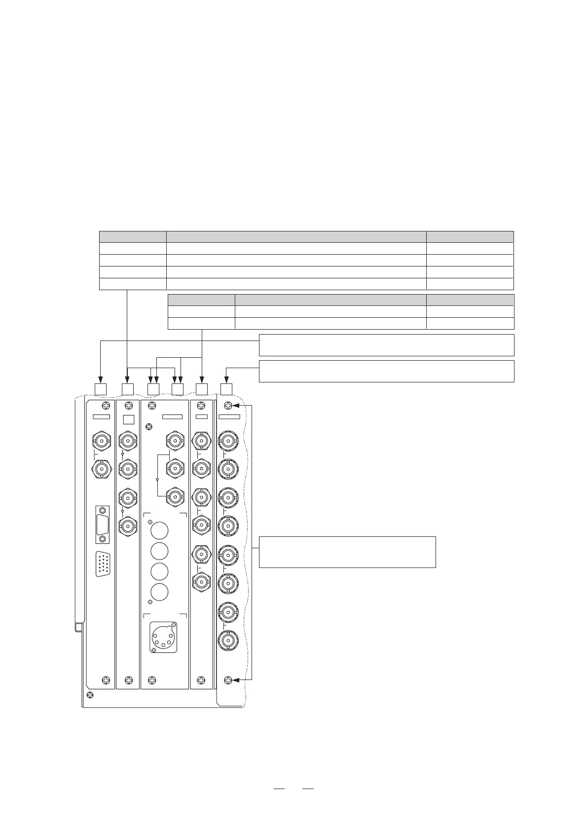
5-1 Option Module
<Notes>
• Modules should be inserted into the slots specified in the figure below.
• Optional modules should be inserted into the slot Nos. 2-5.
(The figure below is an example. These modules may not be installed in the product you purchased.)
• Slot 1 and Slot 6 accept the fixed modules only.
• Remove the blank panel before you mount the module.
• Fix the module securely with the two screws located at top and bottom.
• Loose screws may cause the module to come off or result in poor connector contact.
REMOTE
SERIAL
CH A
CH A
CH A
CH B
CH B
CH 1/2
CH 3/4
CH 5/6
CH 7/8
CH C
Y/G
Pb/B
Pr/R
SYNC
PARALLEL
YPbPr/RGB
MONITOR
OUT
MONITOR OUT
()
CH A
INPUT
CH B
HD/4:2:2 SDI
SDI
4:2:2
NTSC
AUDIO LINE OUT
DKM-511AV
AES/EBS OUT
123456
MODELNO. MODULENAME SLOTWIDTH
DK-801A 4:2:2DigitalComponentModule 1
DKM-511A/B Multi-FormatDigitalModule 1
DKM-511*AV Multi-FormatDigitalModulewithEmbeddedAnalogAudiooutput 2
DKM-511*AVD Multi-FormatDigitalModulewithEmbeddedAudioAES/EBUoutput2
MODELNO. MODULENAME SLOTWIDTH
DE-801 NTSC3LineCombDecoderModule 1
DE-811 NTSC3/PAL-BLineCombDecoderModule 1
MPUModule
ThismoduleisfixedtoSlot1,andcannotbeinsertedtootherslot.
VIDEOPROCESSModule
ThismoduleisfixedtoSlot6,andcannotbeinsertedtootherslot.
Modulefixingscrews
Fixthemodulesecurelybytighteningthesetwo
screwsattopandbottom.
 Loading...