14
3-2. Parallel Remote Connection
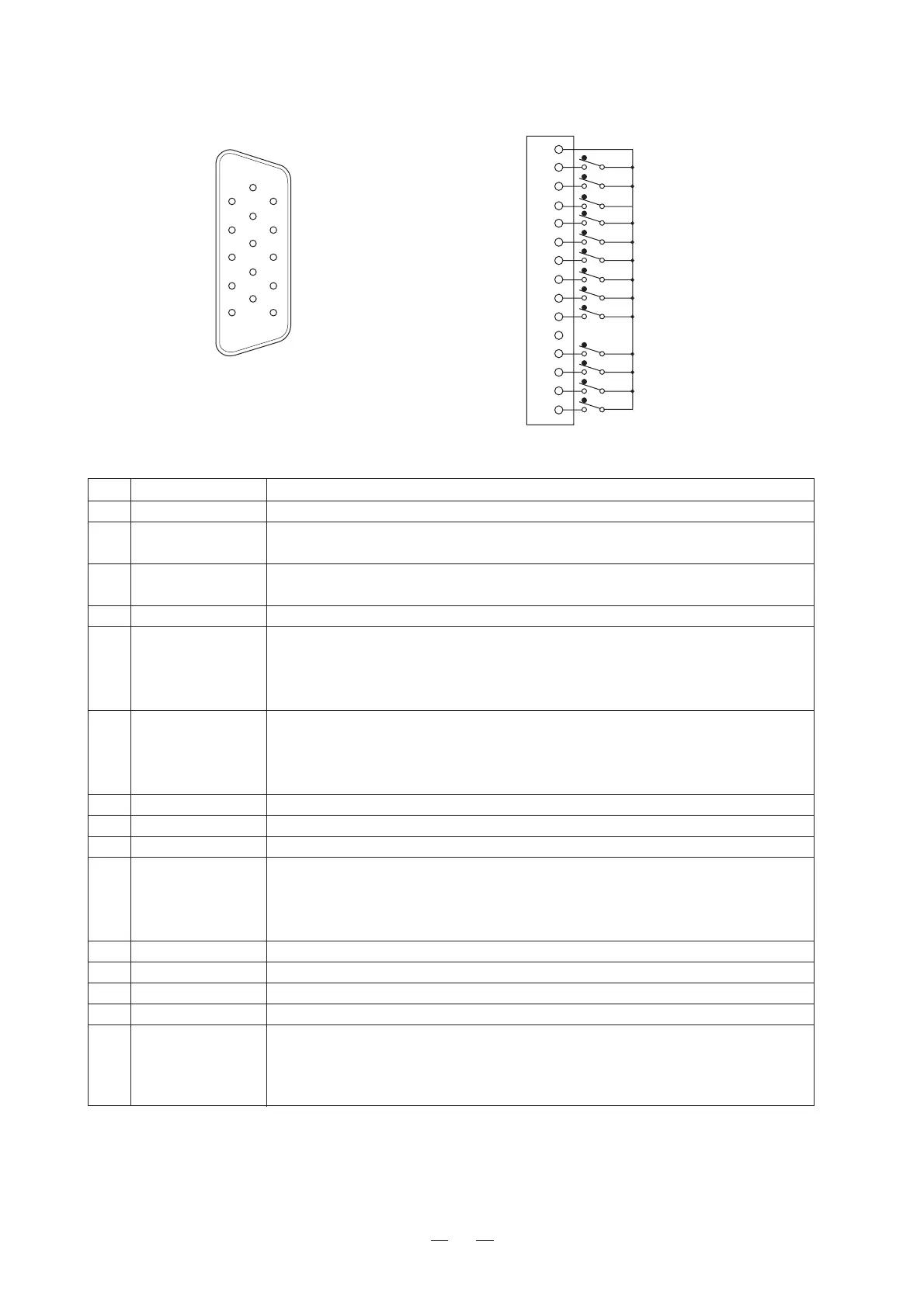
(1) Pin function
111
6
155
10
1
2
3
4
5
6
7
8
9
10
11
12
13
14
15
GND
CH-B ON
CH-C ON
Green TALLY ON
YPbPr/RGB ON
SD-SDI ON
MONO ON
RGB ON
EXT-SYNC ON
16 : 9 ON
NC
MARKER ON
SHADOW ON
Red TALLY ON
HD-SDI/MULTI-SDI
ON
<ConnectorFaceViewonRearPanel>
<WiringofRemoteConnector>
Pin No.
Function External Assignment for Function
1 GND ON Connecting remote terminals to this pin enables ON control.
2 CH-B ON
Connect to Pin 1 to select B channel.
* When Pins 2 and 3 are both OPEN, the A channel will be selected.
3 CH-C ON
Connect to Pin 1 to select C channel.
* When Pins 2 and 3 are both OPEN, the A channel will be selected.
4 Green TALLY ON Connect to Pin 1 to set G TALLY to ON.
Connect to Pin 1 to select the component video (YPbPr/RGB) input.
5 YPbPr/RGB ON
Use together with Pin 2 to switch between channels A and B.
* When Pins 5, 6 and 15 are all OPEN with DE-801/811 mounted, the analog
composite will be selected.
Connect to Pin 1 to select the digital video (SD-SDI) input.
6 SD-SDI ON
Use together with Pin 2 to switch between channels A and B.
* When Pins 5, 6 and 15 are all OPEN with DE-801/811 mounted, the analog
composite will be selected.
7 MONO ON Connect to Pin 1 to switch the COLOR/MONO setting to MONO.
8 RGB ON Connect to Pin 1 to switch the YPbPr/RGB setting to RGB.
9 EXT-SYNC ON Connect to Pin 1 to switch the analog input sync to external sync (EXT SYNC).
Connect to Pin 1 to switch the aspect (4:3/16:9) setting to 16:9.
10 16:9 ON
When the aspect is set to 4:3 for HDTV signal, [HD4:3 SCAN] mode is entered.
If the setting is to be controlled simultaneously with channel switching, set
[CHANGE ASPE] to [MANUAL] in MENU 2-4.
11 N.C No connection
12 MARKER ON Connect to Pin 1 to set 4:3 MARKER to ON.
13 SHADOW ON Connect to Pin 1 to set SHADOW to ON.
14 Red TALLY ON Connect to Pin 1 to set Red TALLY to ON.
Connect to Pin 1 to select the HD-SDI or Multi-SDI input module.
15
HD-SDI/MULTI-SDI ON
Use together with Pin 2 to switch between channels A and B.
* When Pins 5, 6 and 15 are all OPEN with DE-801/811 mounted, the analog
composite will be selected.
(2) Connectors used (Standard accessories)
D-sub 15-pin (male) mini type
•Connector: HDB-15M (3011-15) Made by Japan Aviation Electronics Industry
•Case: HE-C8-J9-F2-1 Made by Japan Aviation Electronics Industry
 Loading...