15
WARNING
POWER
DEGAUSS
OVER LOAD
NO BURST
⑤ ④ ②
②
③
③
①
①
④
⑤
POWER
DEGAUSS
WARNING
OVER LOAD
NO BURST
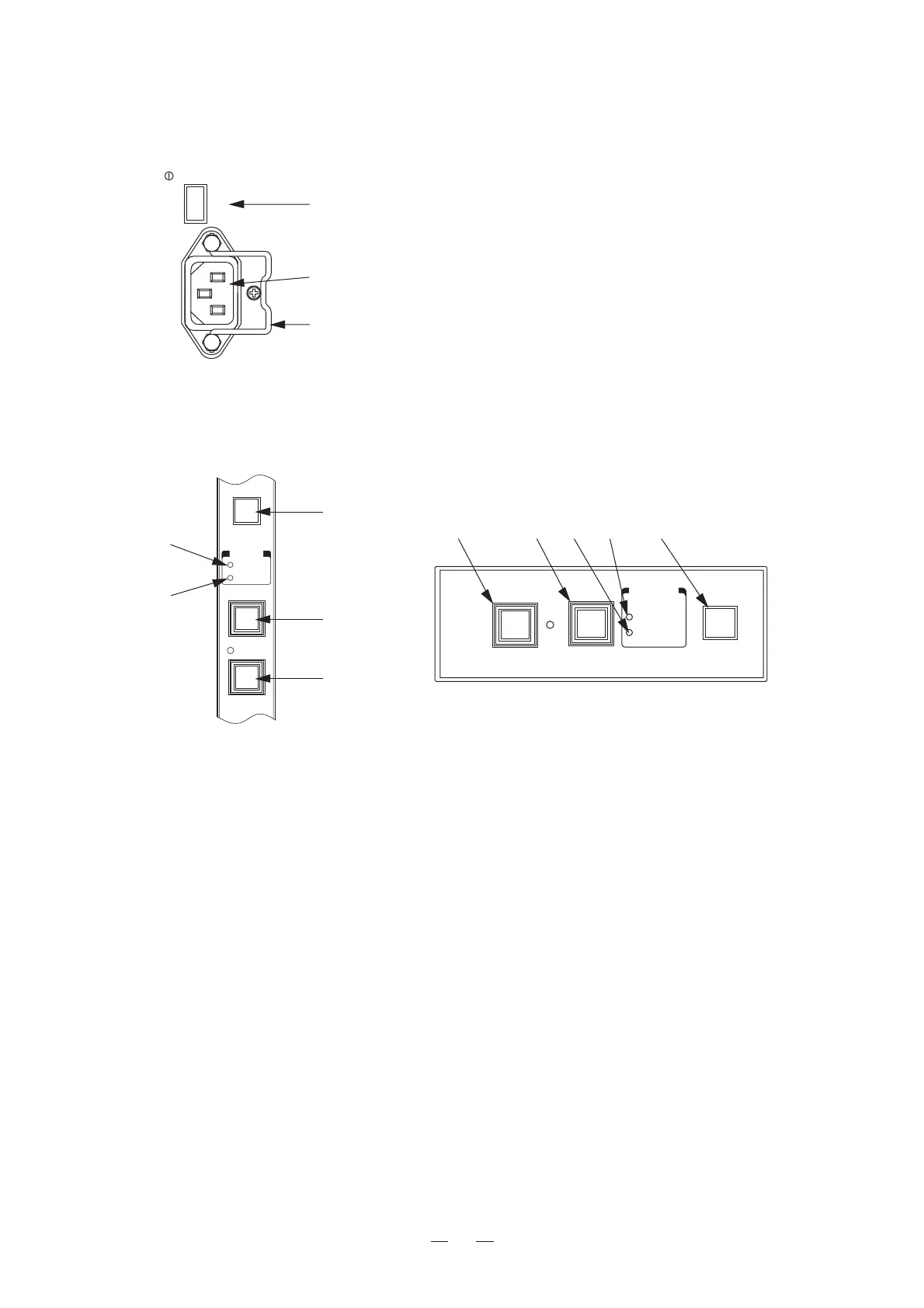
4. User Adjustment
4-1. Power Supply
AC IN
AC100-120V
MAIN
POWER
①MAIN POWER switch
Usedtoturnthemonitor'sACpowerON/OFF.Tooperatethemonitor,turnONthis
MAINPOWERswitchaswellasthePOWERswitchonthefrontpanel.
②AC power input
InserttheprovidedACcableheretosupplyACpower.
③Lock
AfterinsertingtheACplug,locktheACplugwiththislocktopreventitfromdisconnecting.
Fig. 4-1. POWER Section on Rear Panel (common for HTM-1517R and HTM-1917R)
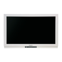
4-2. Names and Functions of Front Left Panel Parts
Fig. 4-2-1. HTM-1517R Front Left Panel
① Infrared sensor
Infrared sensor for the optional wireless remote controller RCT-30A.
② NO BURST LED
LED which operates only when the composite signal input is selected.
The LED lights up when the selected composite signal has no burst (black and white signal) or when the color
killer circuit is activated.
③ OVERLOAD LED
This LED lights up when the ABL circuit is activated (the luminance is higher than necessary).
Using the monitor in a way which causes this LED to light up continuously for a long time will deteriorate the
CRT. Therefore use the monitor with the luminance lowered.
④ DEGAUSS switch
When the power is turned ON, CRT demagnetization will be performed automatically.
This switch allows demagnetization to be performed at one-touch.
As pressing this switch continuously has no effect, release and press again 2 to 3 minutes later.
⑤ POWER switch, LED
Switch for turning the monitor power ON/OFF. The LED is ON when the power is turned ON.
Always turn ON the MAIN POWER switch on the rear panel when starting the monitor.
Normally turn ON/OFF using this switch.
Note that this switch does not turn the monitor's AC power ON/OFF.
Fig. 4-2-2. HTM-1917R Front Left Panel