© 2018 imc Test & Measurement GmbH
imc C-SERIES - Manual, Version 4 R 3 - 2018-10-19
113CS-7008-FD, CL-7016-FD
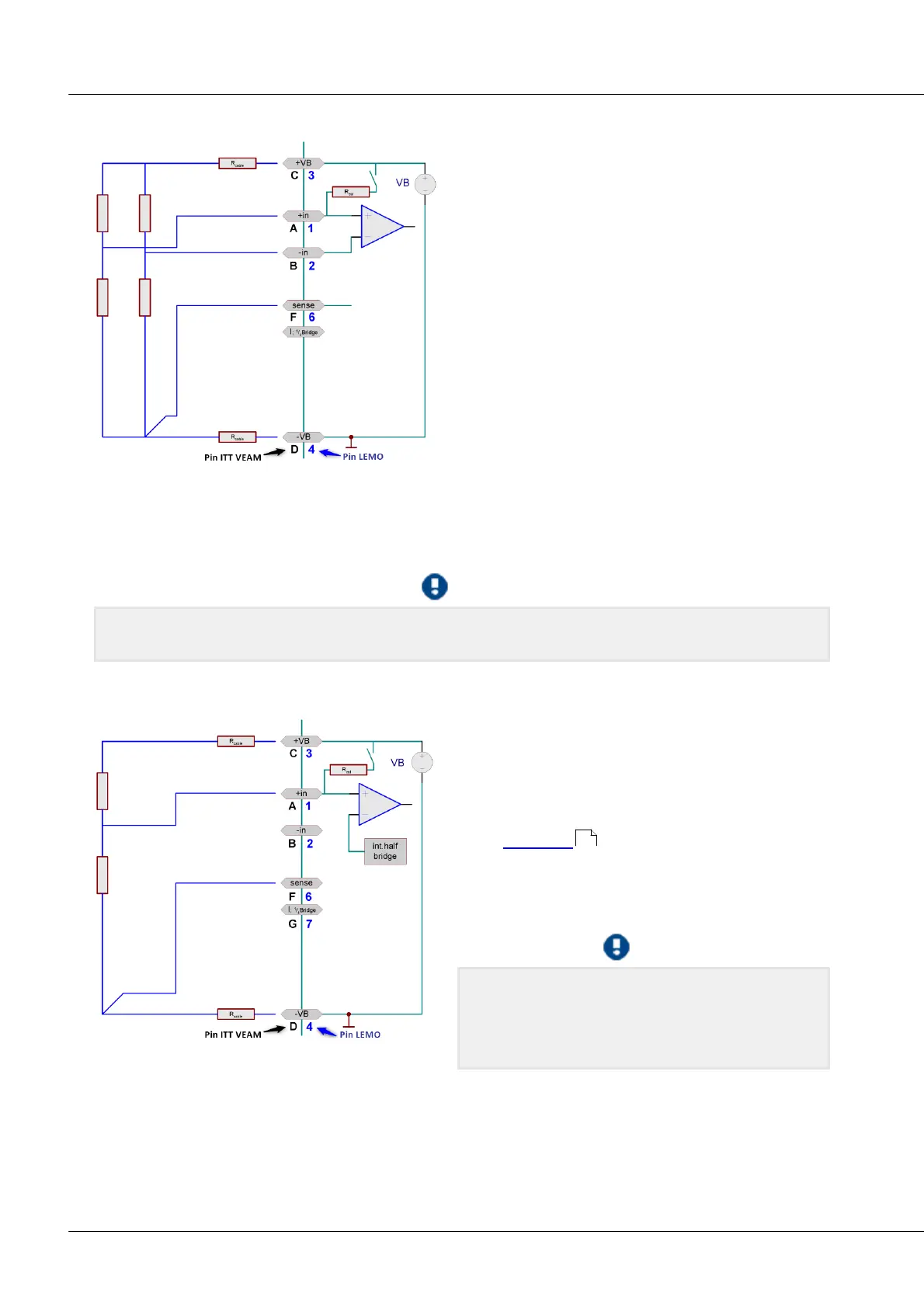
5.8.2.1 Full bridge
A full bridge has four resistors, which can be four
correspondingly configured strain gauges or one
complete sensor which is a full sensor internally. The
full bridge has five terminals to connect. Two leads
+VB and -VB serve supply purposes, two other leads
+IN and -IN capture the differential voltage. The 5th
lead SENSE is the Sense lead for the lower supply
terminal, which is used to determine the single-sided
voltage drop along the supply line. Assuming that
the other supply cable +VB has the same impedance
and thus produces the same voltage drop, no 6th
lead is needed. The Sense lead makes it possible to
infer the measurement bridge's true supply voltage,
in order to obtain a very exact measurement value in
mV/V.
Please note that the maximum allowed voltage drop
along a cable may not exceed approx. 0.5 V. This determines the maximum possible cable length.
If the cable is so short and its cross section so large that the voltage drop along the supply lead is
negligible, the bridge can be connected at four terminals by omitting the Sense line.
For the predecessor model C-70xx pin -SENSE must never be unconnected! In that case, -SENSE and -VB
must be jumpered.
5.8.2.2 Half bridge
A half bridge may consist of two strain gauges in a
circuit or a sensor internally configured as a half
bridge, or a potentiometer sensor. The half bridge
has 4 terminals to connect. For information on the
effect and use of the SENSE lead, see the description
of the full bridge .
The amplifier internally completes the full bridge
itself, so that the differential amplifier is working
with a full bridge.
It is important that the measurement signal of the
half bridge is connected to +IN. The -IN access leads
to implausible measured values and influences the
neighbor channels.
113
 Loading...
