© 2018 imc Test & Measurement GmbH
imc C-SERIES - Manual, Version 4 R 3 - 2018-10-19
114 Device description
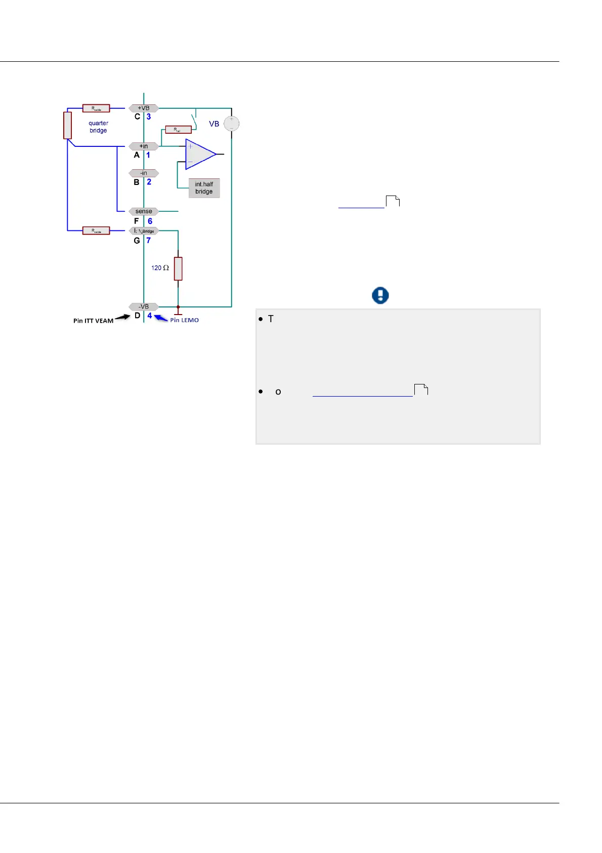
5.8.2.3 Quarter bridge
A quarter bridge can consist of a single strain gauge resistor,
whose nominal value can be 120 Ω or 350 Ω. C-70xx internally
completes an additional 120 Ω that can be switched to a
350 Ω quarter bridge.
For quarter bridge measurement, only 5 V can be set as the
bridge supply.
The quarter bridge has 4 terminals to connect. Refer to the
description of the full bridge for comments on the SENSE
lead. However, with the quarter bridge, the SENSE lead is
connected to +IN and -SENSE jointly. If the sensor supply is
equipped with the option "±15 V", a quarter bridge
measurement is not possible. The pin I_1/4Bridge for the
quarter bridge completion is used for -15 V instead.
·
The predecessor model C-70xx comes with a 120 Ω
internal bridge completion resistor. A 350 Ω internal bridge
completion resistor is alternatively possible for the
purpose of quarter bridge measurement for the
predecessor model C-70xx.
·
No direct current measurement with the standard
included connector ACC/DSUBM-UNI2 is possible, but only
with the optional ACC/DSUBM-I2 connector with a 50 Ω
shunt resistor (differential measurement).
5.8.2.4 Sense and initial unbalance
The SENSE lead serves to compensate voltage drops due to cable resistance, which would otherwise
produce noticeable measurement errors. If there are no sense lines, then C-70xx SENSE (F) must be
connected in the terminal plug according to the sketches above.
A bridge measurement is a relative measurement (ratiometric procedure) that calculates what fraction
of the supplied bridge excitation voltage is given off from the bridge (typically in the 0.1% range,
corresponding to 1 mV/V). Calibration of the system in this case pertains to this ratio, the bridge input
range, and takes into account the momentary magnitude of the supply. This means that the bridge
supply's actual magnitude is not relevant and need not necessarily lie within the measurement's
specified overall accuracy.
Any initial unbalance of the measurement bridge, for instance due to mechanical pre-stressing of the
strain gauge in its rest state, must be zero-balanced. Such an unbalance can be many times the input
range (bridge balancing). If the initial unbalance is too large to be compensated by the device, a larger
input range must be set.
113
118
 Loading...
