C13 C12
1-11
2
1
3
4
7
5
6
2
1
3
4
5
8
7
6
C33 C33
1-13 1-14
1-121-10
11 - IE
INSTALLERUSER
MAINTENANCE TECHNICIAN
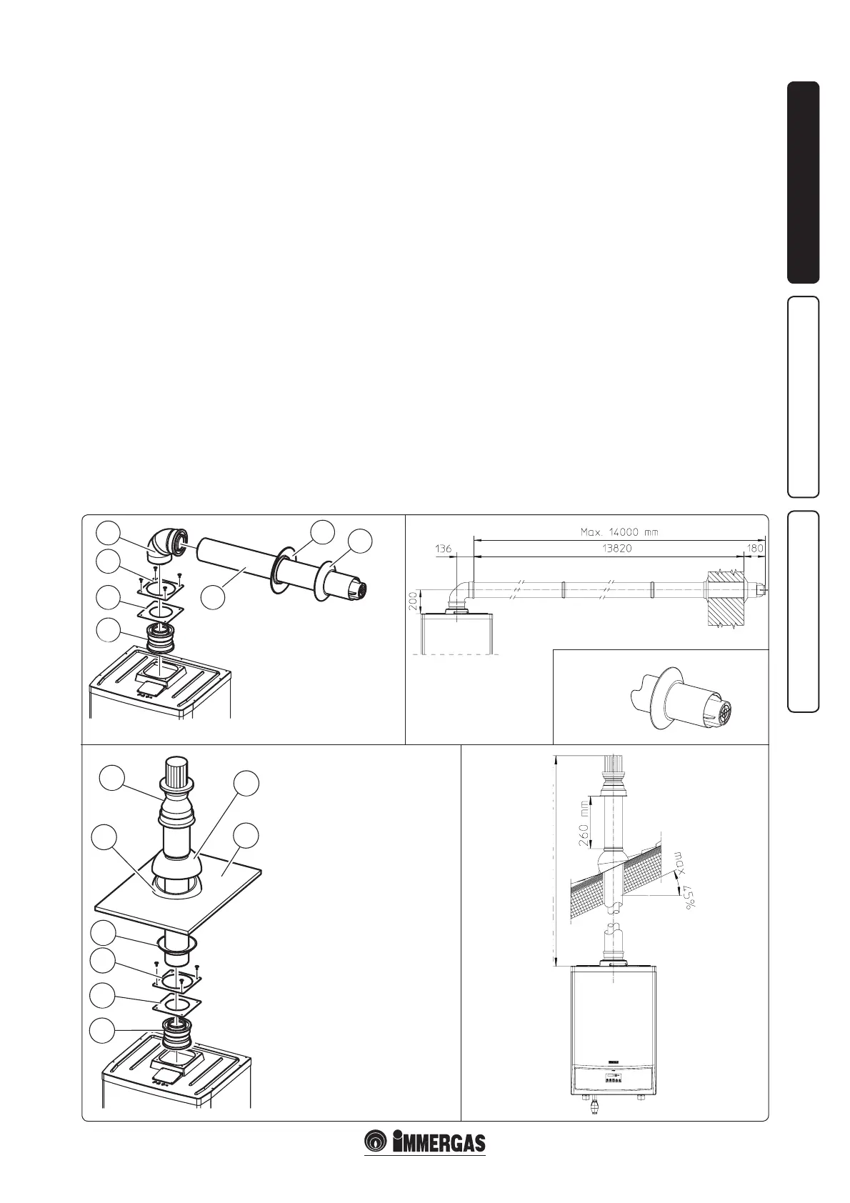
e kit includes:
N° 1 - Adapter Ø80/125 (1)
N° 1 - Gasket (2)
N° 1 - Concentric bend Ø80/125 at
87° (4)
N° 1 - Concentric intake-exhaust
terminal Ø80/125 (5)
N° 1 - Internal wall sealing plate (6)
N° 1 - External wall sealing plate (7)
1.10 BOILER INSTALLATION IN TYPE
"C" CONFIGURATION.
e "Victrix 50" boiler leaves the factory with
"B
23
" configuration (open chamber and fan
assisted), to change the configuration of the
boiler to type "C" (sealed chamber and fan
assisted), disassemble the Ø80 adapter, the
bracket and the gasket present on the boiler cover.
Horizontal intake-exhaust kit Ø80/125
Kit assembly (Fig. 1-10): install the Ø80/125
adapter (1) on the central hole of the boiler fully
home. Slide the gasket (2) along the adapter (1)
up to the relevant groove, Fix it to the lid using
the previously disassembled sheet steel plate (3)
Engage the bend (4) with the male side (smooth)
until it is fully home on the adapter (1). Fit the
Ø80/125 (5) concentric terminal pipe with the
male end (smooth) to the female end of the bend
(4) (with lip seals) up to the stop; making sure
that the internal (6) and external wall sealing
plates (7) have been tted, this will ensure sealing
and joining of the elements making up the kit.
• Coupling extension pipes and concentric
elbows Ø80/125. To push-t extensions with
other elements of the ue extraction elements,
operate as follows Install the concentric pipe
or elbow with the male side (smooth) on the
female section (with lip seal) to the end stop
on the previously installed element. is will
ensure sealing and joining of the elements
correctly.
e kit Ø80/125 can be installed with the rear,
right side, le side or front outlet.
• Extensions for horizontal kit. e horizontal
intake-exhaust kit Ø80/125 can be extended up
to a max. horizontal distance of 14 m (Fig. 1-11)
including the terminal with grid and excluding
the concentric bend leaving the boiler. is
conguration corresponds to a resistance factor
of 100. In these cases the special extensions
must be requested.
N.B.: during the installation of pipes it is
necessary to keep a minimum inclination of 3%
and a dividing strip with gusset must be installed
every 3 metres.
• External grille (Fig. 1-12). The Ø80/125
intake/exhaust terminal, if properly installed,
is pleasant to look at on the outside of the
building. Make sure that the external silicone
sealing plate is properly inserted in the wall.
N.B.: for safety purposes, do not obstruct the
boiler intake-exhaust terminal, even temporarily.
Vertical kit with aluminium tile Ø80/125.
Kit assembly (Fig. 1-13): install the Ø80/125
adapter (1) on the central hole of the boiler fully
home. Slide the gasket (2) along the adapter (1)
up to the relevant groove, Fix it to the lid using
the previously disassembled sheet steel plate (3)
Imitation aluminium tile installation: replace
the tile with the aluminium sheet (5), shaping
it to ensure that rainwater runs o. Position
the xed half-shell (6) on the aluminium tile
and insert the intake-exhaust pipe (7). Fit the
Ø80/125 concentric terminal pipe with the male
end (smooth) to the female end of the adapter
(1) (with lip gaskets) up to the stop; making sure
that the wall sealing plate (4) has been tted, this
will ensure sealing and joining of the elements
making up the kit.
• Coupling extension pipes and concentric
elbows Ø80/125. To snap-t extensions with
other elements of the ue extraction elements,
operate as follows: Install the concentric pipe
or elbow with the male side (smooth) on the
female section (with lip seal) to the end stop
on the previously installed element in order to
ensure sealing eciency of the coupling.
Attention: if the exhaust terminal and/or
extension concentric pipe needs shortening,
consider that the internal duct must always
protrude by 5 mm with respect to the external
duct.
e kit includes:
N° 1 - Adapter Ø80/125 (1)
N° 1 - Gasket (2)
N° 1 - Wall sealing plate (4)
N° 1 - Aluminium tile (5)
N° 1 - Fixed half-shell (6)
N° 1 - Concentric intake-exhaust
terminal Ø80/125 (7)
N° 1 - Mobile half-shell (8)
MAXIMUM LENGTH 18000 mm