3-1
24 - IE
INSTALLERUSER
MAINTENANCE TECHNICIAN
3
BOILER COMMISSIONING
INITIAL CHECK
To commission the boiler:
- ensure that the declaration of conformity of
installation is supplied with the appliance;
- ensure that the type of gas used corresponds to
boiler settings;
- check connection to a 230V-50Hz power
mains, correct L-N polarity and the earthing
connection;
- make sure the heating system is lled with
water and that the manometer indicates a
pressure of 1÷1.2 bar;
- switch the boiler on and ensure correct ignition;
- check the CO
2
in the combustion products at
maximum and minimum ow rate;
- check that the no. of fan revs is that indicated
in the book (Par. 3.21);
- check activation of the safety device in the event
of no gas, as well as the relative activation time;
- check activation of the main switch located
upstream from the boiler and in the boiler;
- check the existing draught during normal
functioning of the appliance, e.g. a draught
gauge positioned at the exit of the appliance
combustion products;
- check that there is no backow of combustion
products into the room, even during
functioning of fans;
- check that the intake and/or exhaust terminals
are not blocked;
- ensure activation of all adjustment devices;
- seal the gas ow rate regulation devices (if
settings are modied);
- ensure sealing eciency of water circuits;
- check ventilation and/or aeration of the
installation room where provided.
If even only a single safety check oers a negative
result, do not commission the system.
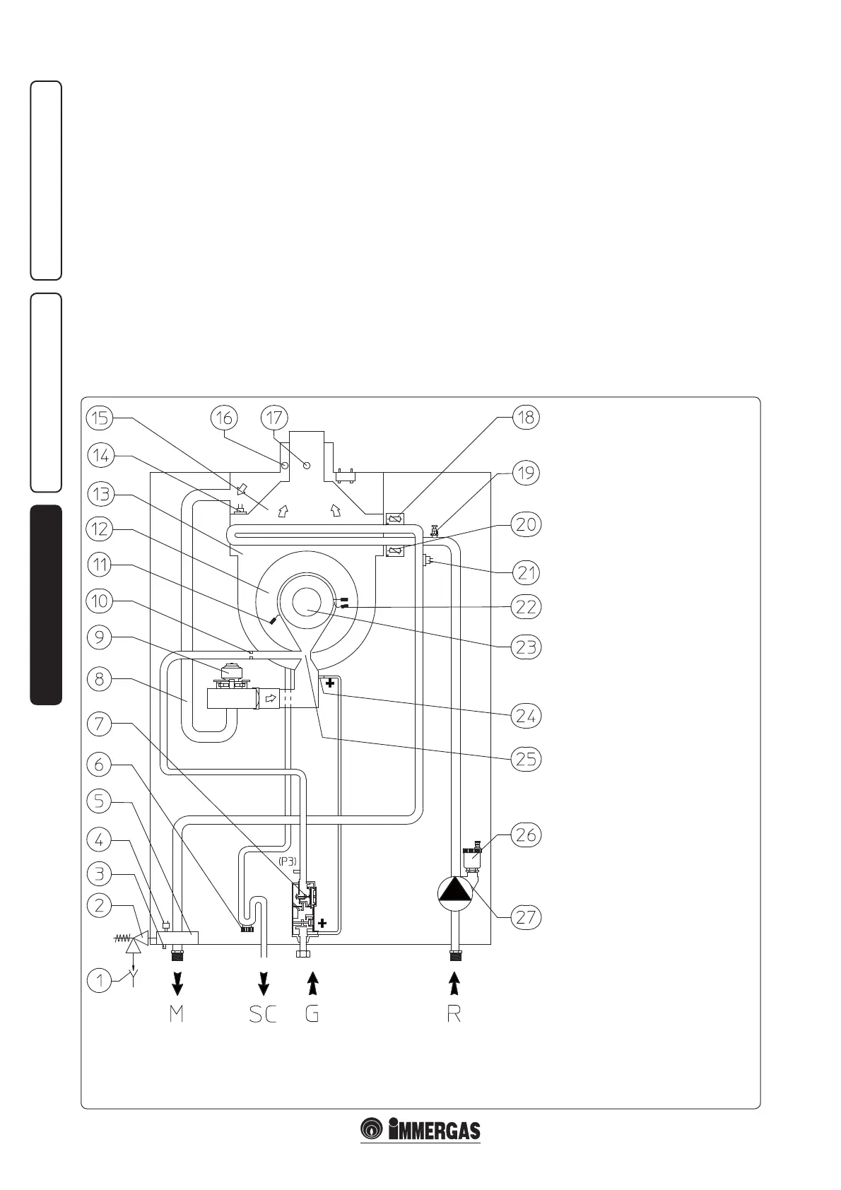
3.1 HYDRAULIC DIAGRAM.
Key:
1 - Draining funnel on view
2 - 4 bar safety valve
3 - Boiler draining valve
4 - Absolute pressure switch
5 - Flow collector
6 - Condensate trap siphon
7 - Gas valve
8 - Air intake pipe
9 - Air fan
10 - Gas nozzle
11 - Detection electrode
12 - Condensation module cover
13 - Condensation module
14 - Flue safety thermostat
15 - Flue hood
16 - Air sample point
17 - Flue sample point
18 - System ow regulation probe
19 - Manual air vent valve
20 - System return regulation probe
21 - Over-heating safety thermostat
22 - Ignition electrode
23 - Burner
24 - Venturi pipe positive sign (P1)
25 - Air/gas Venturi pipe collector
26 - Automatic air vent valve
27 - Boiler pump
M - System ow
SC - Condensate drain
G - Gas supply
R - System return