1-3 1-4
1-5
7 - IE
INSTALLERUSER
MAINTENANCE TECHNICIAN
1.7 ATTACHMENTS.
Gas connection (Appliance category II
2H3B/P
).
Our boilers are built to function with methane
gas (G20) and L.P.G. e supply piping must be
the same or greater than the 3/4” G boiler tting.
N.B.: the gas supply pipe must be suitably
dimensioned according to current regulations
in order to guarantee correct gas ow to the
boiler even in conditions of maximum generator
output and to guarantee appliance efficiency
(technical specications). e coupling system
must conform to standards.
Before connecting the gas line, carefully clean
inside all the fuel feed system pipes to remove any
residue that could impair boiler eciency. Also
make sure the gas corresponds to that for which
the boiler is prepared (see boiler data-plate).
If dierent, the appliance must be converted
for operation with the other type of gas (see
converting appliance for other gas types). e
dynamic gas supply (methane or LPG) pressure
must also be checked according to the type used
in the boiler, which must be in compliance, as
insucient levels can reduce generator output
and cause malfunctions.
Ensure correct gas cock connection by following
the mounting instructions (Fig. 1-3).
A manual cut-off valve with quick closure
manoeuvre for 90° rotation and end run stops
in the all open or all closed positions must be
installed on the gas supply pipe in a visible and
easily reachable position outside the room where
the appliance is installed.
N.B.: the internal gas supply system must be
in compliance with the provisions of the local
Laws in force.
Fuel gas quality. The appliance has been
designed to operate with gas free of impurities;
otherwise it is advisable to fit special filters
upstream from the appliance to restore the
purity of the gas.
Storage tanks (in case of supply from LPG
depot).
- New LPG storage tanks may contain residual
inert gases (nitrogen) that degrade the mixture
delivered to the appliance casing functioning
anomalies.
- Due to the composition of the LPG mixture,
layering of the mixture components may occur
during the period of storage in the tanks. is
can cause a variation in the heating power of
the mixture delivered to the appliance, with
subsequent change in its performance.
Hydraulic connection.
Important: in order not to void the warranty
before making the boiler connections, carefully
clean the heating system (pipes, radiators, etc.)
with special pickling or descaling products to
remove any deposits that could compromise
correct boiler operation.
A chemical treatment of the thermal system
water is required, in compliance with the
technical standards in force, in order to protect
the system and the appliance from deposits (e.g.,
lime scale), slurry or other hazardous deposits.
It is recommended to prepare a filter in the
system to collect and separate any impurities
present in the system (slurry remover lter). In
order to avoid deposits, scaling and corrosion in
the central heating system, the provisions given
in the regulations on water treatment in heating
systems for civil use must be respected.
Water connections must be made in a rational
way using the couplings on the boiler template.
e discharge of the boiler safety valve must be
connected to a discharge funnel that is present in
the boiler but not installed and then connected
to a sewer. Otherwise, the manufacturer declines
any responsibility in case of ooding if the drain
valve cuts in.
Important: to preserve the duration of appliance
eciency features, we recommend installation of
a suitable device for water treatment in presence of
water whose characteristics can lead to the deposit
of lime scale.
Condensate drain. To drain the condensate
produced by the appliance, it is necessary
to connect to the drainage system by means
of acid condensate resistant pipes having an
internal diameter of at least 13 mm. e system
connecting the appliance to the drainage system
must be carried out in such a way as to prevent
freezing of the liquid contained in it. Before
appliance start-up, ensure that the condensate
can be correctly removed. Also, comply with
national and local regulations on discharging
waste waters.
Electrical connection: The electrical system
must be made in compliance with the local laws
in force. e boiler has an IPX5D protection
rating for the entire appliance. Electrical safety of
the appliance is reached only when it is correctly
connected to an efficient earthing system as
specied by current safety standards.
Attention: Immergas S.p.A. declines any
responsibility for damage or physical injury
caused by failure to connect the boiler to an
ecient earth system or failure to comply with
the reference standards.
Also ensure that the electrical installation
corresponds to maximum absorbed power
specications as shown on the boiler data-plate.
Boilers are supplied complete with an “X” type
power cable without plug. e power supply
cable must be connected to a 230V ±10% /
50Hz mains supply respecting L-N polarity and
earth connection
. is network must also
have an omnipolar circuit breaker with class III
over-voltage category. e main switch must be
installed outside the rooms in a position that
is indicated and accessible. When replacing
the power supply cable, contact a qualified
technician (e.g. the Immergas After-Sales
Technical Assistance Service). e power cable
must be laid as shown in the gure below.
In the event of mains fuse replacement on the
connection terminal board, use a 2A fast fuse. For
the main power supply to the appliance, never
use adapters, multiple sockets or extension leads.
If during connection the L-N polarities are
not respected, the boiler does not detect ame
presence and goes into ignition block.
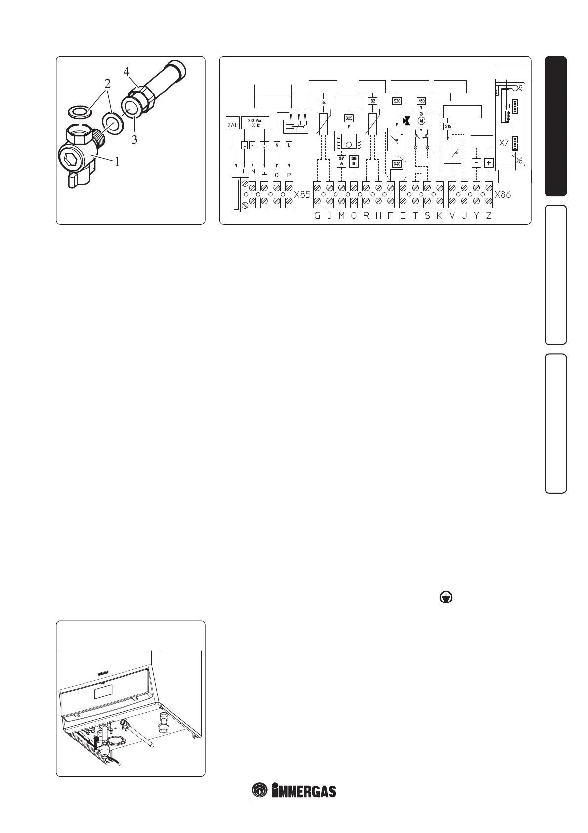
Key:
1 - Gas cock (EN 331)
2 - Flat gasket
3 - Gas pipe
4 - Nut
Cable for
Power Supply
External relay
(optional)
External
pump
(optional)
230 VAC coil
MAX 0.1 A
External probe
(optional)
Heat adjuster
(OPTIONAL)
Room thermostat
(OPTIONAL)
3-Way Valve
(OPTIONAL)
Summer Switch
(OPTIONAL)
Analogue
input
Clip in for cascade
addresses management
Data download
serial interface
Boiler probe
(OPTIONAL)
FUSE