2
1
1-15
B23
B23 B23
1-16 1-17
12 - IE
INSTALLERUSER
MAINTENANCE TECHNICIAN
is specic terminal enables ue exhaust and
air intake, necessary for combustion, in a vertical
direction.
e Ø80/125 vertical kit with aluminium tile
enables installation on terraces and roofs with a
maximum slope between 25% and 45% (24°), the
height between the terminal cap and half-shell
(260 mm) must always be respected.
The vertical kit with this configuration can
be extended up to a maximum of 18 vertical
rectilinear metres (Fig. 1-14), including the
terminal. is conguration corresponds to a
resistance factor of 100. In this case the special
extensions must be requested.
1.11 BOILER INSTALLATION IN TYPE
"B
23
" CONFIGURATION.
e "Victrix 50" boiler leaves the factory with
type "B
23
" configuration (open chamber and
fan assisted).
Air intake takes place directly from the
environment in which the boiler is installed
via relevant slots made in the back of boiler and
ue exhaust in individual ue or to the outside.
e boiler in this conguration the boiler is
classied as type B
23
.
With this conguration:
- air intake takes place directly from the room
in which the appliance is installed;
- the ue exhaust must be connected to its own
individual ue or channelled directly into the
external atmosphere.
- Type B open chamber boilers must not be
installed in places where commercial, artisan
or industrial activities take place, which use
products that may develop volatile vapours
or substances (e.g. acid vapours, glues, paints,
solvents, combustibles, etc.), as well as dusts
(e.g. dust deriving from the working of
wood, coal nes, cement, etc.), which may be
damaging for the components of the appliance
and jeopardise functioning.
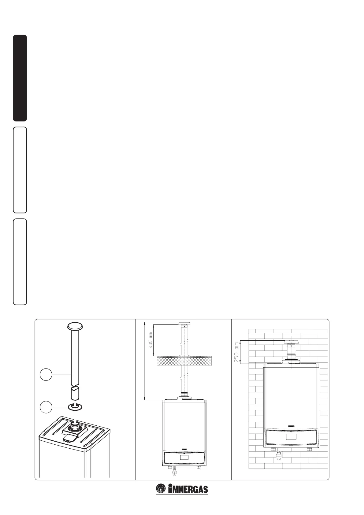
Vertical kit Ø80.
Kit assembly (Fig. 1-15): install the Ø80 terminal
(2) on the central hole on the boiler up to stop,
making sure that the wall sealing plates (1) have
been tted. is will ensure the sealing eciency
of the kit components.
• Coupling of extension pipes and elbows. To
install push-fitting extensions with other
elements of the ue, proceed as follows: Couple
the pipe or elbow with the male side (smooth)
in the female side (with lip seal) to the end stop
on the previously installed element. is will
ensure sealing eciency of the coupling.
• Extensions for vertical exhaust kits. The
maximum vertical straight length (without
bends), used for Ø80 exhaust pipesis 30 metres
(Fig. 1-16).
Using the Ø80 vertical terminal for direct
discharge of the combustion products, the
terminal must be shortened (see quotas g. 1-17).
e wall sealing plate (1) must also be inserted
in this case going up to stop on the boiler cover.
e kit includes:
N° 1 - Wall sealing plate
(1)
N° 1 - Exhaust terminal
Ø80 (2)
MAXIMUM LENGTH 30 m