1-24
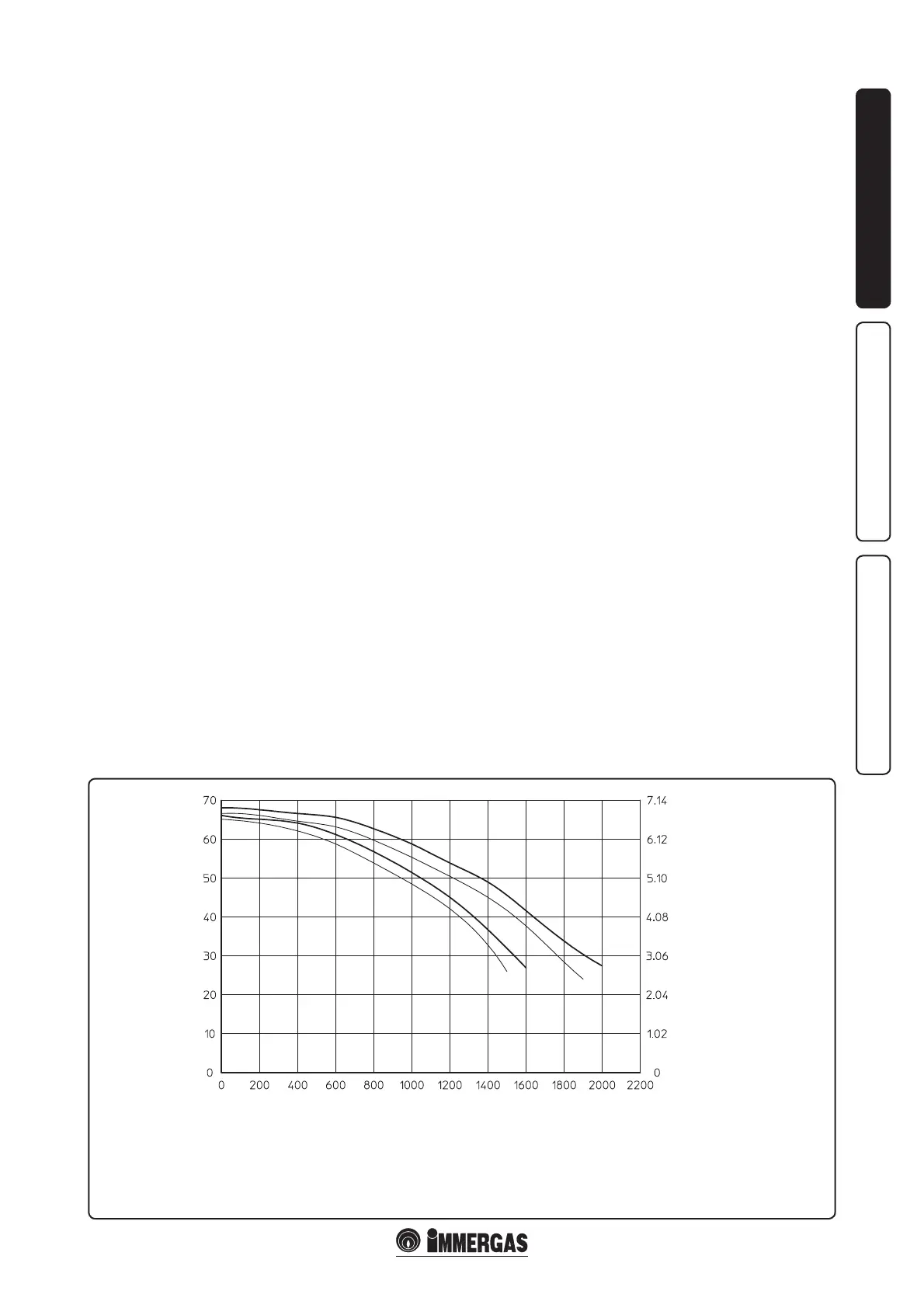
A
C
B
D
15 - IE
INSTALLERUSER
MAINTENANCE TECHNICIAN
Head available to the system.
1.16 GAS SYSTEM STARTUP.
To start up the system, make reference to the
Standard: is divides the systems and therefore
the start-up operations into three categories: new
systems, modied systems, re-activated systems.
In particular, for new gas systems:
- open windows and doors;
- avoid presence of sparks or naked ames;
- bleed all air from pipelines;
- check that the internal system is properly sealed
according to the regulations in force.
1.17 BOILER START UP IGNITION.
For issue of the Declaration of Conformity
provided for by Italian Law, the following must
be performed for boiler start-up:
- check that the internal system is properly sealed
according to the regulations in force;
- ensure that the type of gas used corresponds to
boiler settings;
- switch the boiler on and ensure correct ignition;
- check that the no. of fan revs is that indicated
in the book (Par. 3.21);
- ensure that the safety device is engaged in the
event of gas supply failure and check activation
time;
- check activation of the master switch located
upstream from the boiler and in the boiler;
- check that the concentric intake-exhaust
terminal (if tted) is not blocked.
e boiler must not be started up even if only
one of the checks should be negative.
N.B.: the boiler preliminary check must be carried
out by a qualied technician. e conventional
boiler warranty is valid as of the date of testing.
e test certicate and warranty is issued to the
user.
1.18 CIRCULATION PUMP.
e “Victrix 50” series boilers are supplied with
a built-in circulation pump with 3-position
electric speed control. e boiler does not operate
correctly with the circulation pump on first
speed. To ensure optimal boiler operation, in the
case of new systems (single pipe and module) it
is recommended to use the pump at maximum
speed. e circulation pump is already tted
with a capacitor.
Pump release. If, aer a prolonged period of
inactivity, the circulation pump is blocked,
unscrew the front cap and turn the motor sha
using a screwdriver. Take great care during this
operation to avoid damage to the motor.
1.19 KITS AVAILABLE ON REQUEST.
• Cascade and zones heat adjuster kit.
• Support kit for xing the heat adjuster to the
wall.
• Zone manager kit.
• Modulating room thermostat kit.
• External probe kit.
• System ow probe kit.
• DHW probe kit for external storage tank.
• Anti-freeze kit with -15°C resistance.
• Individual boiler safety devices stub pipes kit.
• Boilers in cascade safety devices stub pipes kit.
• Three-way valve kit for coupling external
storage tank unit.
• Individual boiler hydraulic circuit breaker kit.
• Hydraulic connection collectors kit with two
boilers in cascade.
• Additional boiler in cascade hydraulic collector
kit.
• Flue exhaust collector kit with ue adjusting
devices with two boilers in cascade.
• Flue exhaust collector kit with ue adjusting
device with additional boiler in cascade.
• Ø80/125 horizontal concentric kit.
• Ø80/125 vertical concentric kit.
• Ø80 horizontal kit with ue exhaust.
• Ø80 horizontal terminal kit with wall flue
exhaust.
• Ø80 vertical terminal kit.
e above-mentioned kits are supplied complete
with instructions for assembly and use.
A = Head available to the system on the individual boiler maximum speed
B = Head available to the system on the individual boiler second speed
C = Head available to the system on maximum speed with non-return valve for boilers in cascade (set)
D = Head available to the system on second speed with non-return valve for boilers in cascade (set)
Head (m H
2
O)
Flow rate (l/h)
Head (kPa)