1-27
1-28
18 - IE
INSTALLERUSER
MAINTENANCE TECHNICIAN
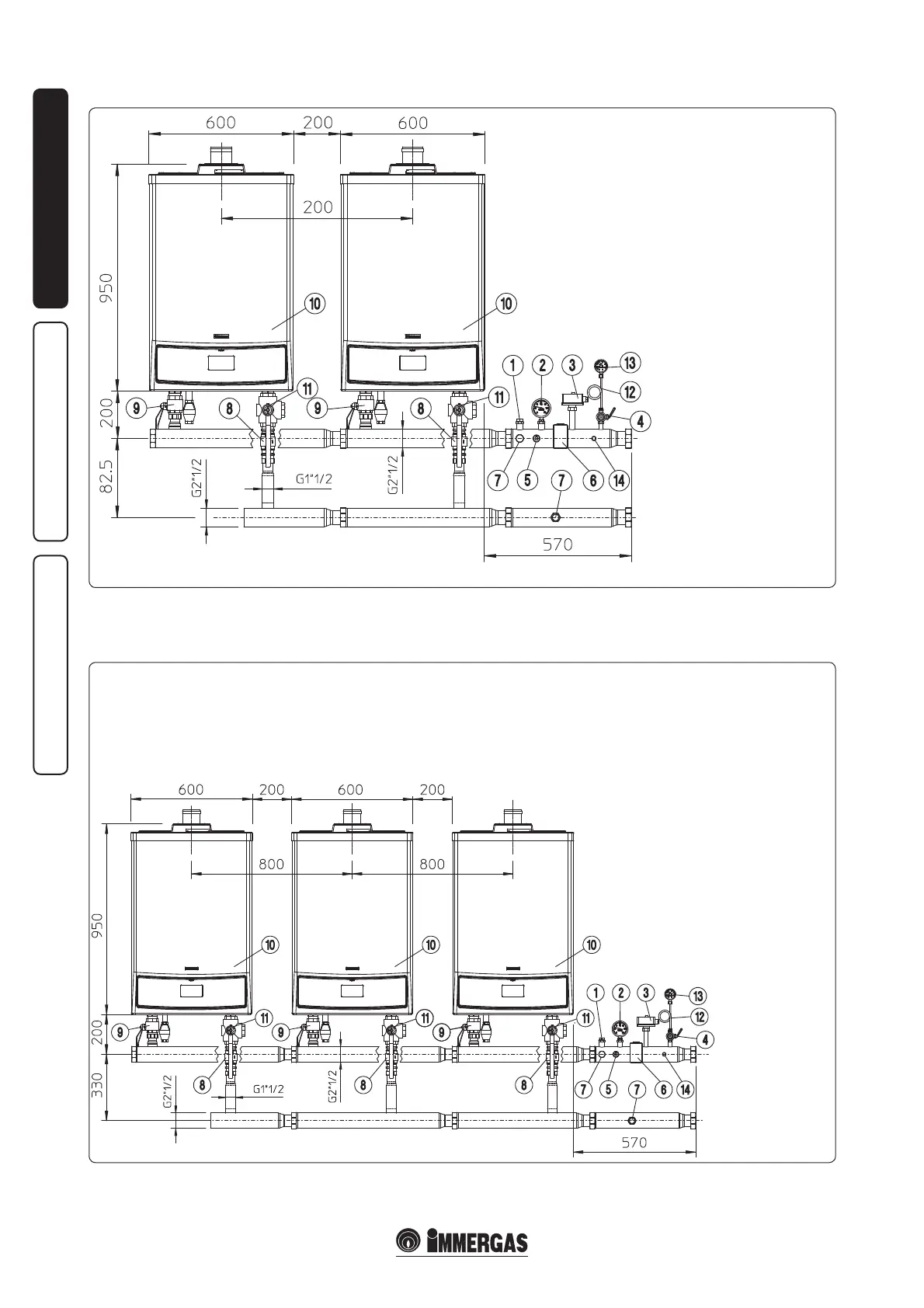
1.22 HYDRAULIC DIAGRAM FOR NO. 2 BOILERS IN CASCADE WITH OPTIONAL.
Attention: the modular boilers, i.e. installed
in cascade (set) with an Immergas original
Key:
1 - ermometer pocket
2 - ermometer
3 - Manual rearm thermostat
4 - Manometer-holder cock
5 - Probe for fuel shut-o valve bulb
6 - Manual rearm pressure switch
7 - Attachment for expansion vessel
8 - System return non-return valve
9 - System cut-o valves
10 - Generator
11 - ree-way draining valve
12 - Damper coil
13 - Manometer
14 - Connection for minimum pressure switch
1.23 HYDRAULIC DIAGRAM FOR NO. 3 BOILERS IN CASCADE WITH OPTIONAL.
Attention: the modular boilers, i.e. installed
in cascade (set) with an Immergas original
connection kit, must be considered a unique
appliance, which assumes the serial number
(factory number) of the boiler nearest to the
safety devices.
Key:
1 - ermometer pocket
2 - ermometer
3 - Manual rearm thermostat
4 - Manometer-holder cock
5 - Probe for fuel shut-o valve bulb
6 - Manual rearm pressure switch
7 - Attachment for expansion vessel
8 - System return non-return valve
9 - System cut-o valves
10 - Generator
11 - ree-way draining valve
12 - Damper coil
13 - Manometer
14 - Connection for minimum pressure
switch
connection kit, must be considered a unique
appliance, which assumes the serial number
N.B.: before closing one or both the system cut-
o cocks (9), the boiler must be switched o.
(factory number) of the boiler nearest to the
safety devices.