1-6 1-7 1-8
45
31
58
8 - IE
INSTALLERUSER
MAINTENANCE TECHNICIAN
Attention: also in the case in which the L-N
polarity is not respected, if there is temporary
residual voltage exceeding 30V on the neutral,
the boiler could function all the same (but
only temporarily). Measure the voltage using
appropriate instruments, without trusting the
voltage tester screwdriver.
1.8 COMMANDS FOR HEAT
ADJUSTMENT OPTIONAL.
e boiler is prepared for the application of a
cascade and zone regulator, zone manager and
external probe.
ese components are available as separate kits
to the boiler and are supplied on request.
Carefully read the user and assembly instructions
contained in the accessory kit.
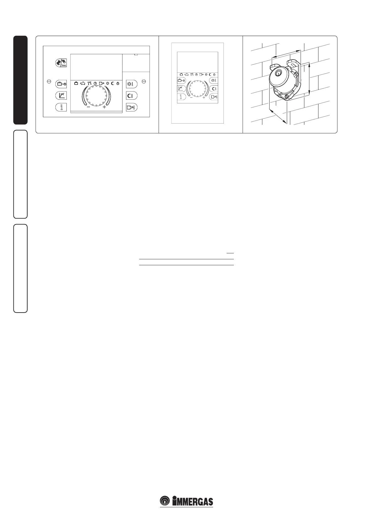
• e cascade and zone regulator (Fig. 1-6) is
connected to the boiler using only two wires,
powered at 230 V and allows to:
- manage a hydraulic circuit with 2 mixed
zones (mixing valve); 1 direct zone; 1 Storage
tank unit and relative pumps;
- self-diagnosis system to display any boiler
functioning anomalies;
- to set two room temperature values: one for
day (comfort temperature) and one for night
(lower temperature);
- to manage the temperature of the DHW (with
a storage tank unit);
- to manage the boiler flow temperature
depending on the external temperature;
- to select the desired operating mode from
the various possible alternatives for each
individual hydraulic circuit:
- permanent operation in comfort temp;
- permanent operation in lower temp;
- permanent operation in adjustable anti-freeze
temp.
• Zone manager (Fig. 1-7). In addition to the
functions described in the previous point, the
zone manager panel allows to control all the
important information regarding operation
of the appliance and the heating system with
the opportunity of easily intervening on the
previously set parameters without having to
go to the place where the appliance is installed.
e climate chrono-thermostat incorporated
into the remote panel enables the system ow
temperature to be adjusted to the actual needs
of the room being heated, in order to obtain
the desired room temperature with extreme
precision and therefore with evident saving
in running costs. It also allows to display the
eective room temperature and the external
temperature (if external probe is present).
e zone manager is powered directly by the
cascade heat adjuster via 2 wires.
• External temperature probe (Fig. 1-8). e
probe can be connected directly to the boiler
electrical system and allows the max. system
ow temperature to be automatically decreased
when the external temperature increases,
in order to adjust the heat supplied to the
system according to the change in external
temperature. The external probe always
operates when connected, regardless of the
presence or type of heat adjuster used and can
work in combination with both heat adjusters.
e electric connection of the external probe
must take place on clamps G and J on the X86
connection of the boiler. (Fig. 1-4).
Cascade and zone regulator electric connection
or On/o chrono-thermostat (Optional). e
operations described below must be performed aer
having removed the voltage from the appliance.
Any thermostat or On/O environment chrono-
thermostat must be connected to clamps “E” and
“F” eliminating jumper X40 (Fig. 1-4). Make
sure that the On/O thermostat contact is of the
“clean” type, i.e. independent of the mains supply,
otherwise the P.C.B. would be damaged. Any
cascade and zone regulator must be connected
using clamps 37 and 38 to clamps “M” and “O”
on the X86 connection terminal board (in boiler)
respecting the polarity eliminating jumper X40,
(Fig. 1-4) the connection with incorrect polarity,
even if not damaging the heat adjuster, does not
allow its functioning.
Important: if the Digital Remote Control is used,
arrange two separate lines in compliance with
current regulations regarding electrical systems.
No boiler pipes must ever be used to earth
the electric system or telephone lines. Ensure
elimination of this risk before making the boiler
electrical connections.
Installation with system operating at direct
low temperature. e boiler can directly feed a
low temperature system, varying the maximum
ow temperature of the boiler and setting a value
between 20 e 85°C. To vary the maximum ow
temperature of the boiler, modify the maximum
ow temperature of the boiler of parameter No. 4
according to the "parameters mode" procedure.
In this situation it is good practice to insert a
safety device in series with the power supply and
boiler. is device is made up from a thermostat
with a temperature limit of 55°C. e thermostat
must be positioned on the system ow pipe at a
distance of over 2 metres from the boiler.