3-2
12
6
7
11
9
13
14
15
10
16
9
6
9
16
6
7
14
10
11
9
16
9
13
16
9
15
12
18
17
13
9
16
10
9
10
5
6
7
8
9
10
3
4
2
8
6
7
14
13
14
13
13
16
9
19
20
1
12
25 - IE
INSTALLERUSER
MAINTENANCE TECHNICIAN
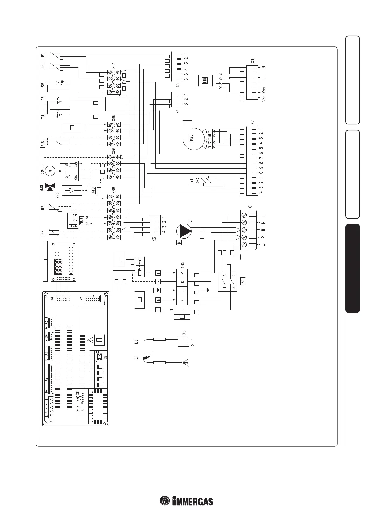
e Bus connection of clamps M and O are used
to manage the boilers in cascade.
e jumper X40 must be eliminated whenever
the room thermostat or cascade regulator are
connected.
3.2 WIRING DIAGRAM.
For safety reasons the P.C.B. envisions a fuse
that cannot be restored in series with the electric
power supply of the gas valve.
Key:
B1 - Flow probe
B2 - DHW probe (optional)
B4 - External temperature probe (optional)
B5 - Return probe
E1 - Ignition electrode
E2 - Detection electrode
E4 - Safety thermostat
E6 - Flue safety thermostat
M1 - Boiler pump
M20 - Fan
M30 - 3-way valve (optional)
S1 - Main switch
S5 - System pressure switch micro switch
S16 - Summer switch (not supplied by Immergas)
S20 - ON/OFF room thermostat (optional)
T10 - Low voltage transformer
X40 - Room thermostat jumper
Y1 - Gas valve (24 Vdc)
1 - Display board
2 - Analogue input
3 - 230 Vac 50Hz
4 - External pump (Optional)
5 - Fuse
6 - Brown
7 - Blue
8 - Yellow/Green
9 - Black
10 - Grey
11 - Orange
12 - White Brown
13 - White
14 - Purple
15 - White Blue
16 - Red
17 - Domestic hot water
18 - Central heating
19 - External relay (Optional)
20 - Coil 230 Vac Max. 0.1A