15
Cable and Control Terminal Connection
All terminals for the control cables are located under the
protective cover of the Ingersoll Rand 302 Series VFD.
The protective cover can be removed using care. All
terminals to the control cables are located beneath the
LCP. They are accessed by removing the cover or
opening the door.
Max. 16 AWG (4.0mm2) wire for all Ingersoll Rand
302 Series VFD models.
Transducer Installation
The Ingersoll Rand 302 Series VFD utilizes the signal
from an electronic pressure sensor. The pressure sensor
must be located where it will see the discharge air
pressure of the compressor.
1. Compressor Package Discharge Pressure
Transducer
2. Ingersoll Rand 302 Series VFD Discharge
Pressure Transducer
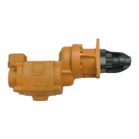
A pressure transducer (4-20 mA; 0-200 psig / 0-13.8
barg) has been provided as a feedback sensor for the
Ingersoll Rand 302 Series VFD.
It is recommended that the transducer receives its
pressure signal from discharge of the compressor.
The pressure sensor must be connected to the Ingersoll
Rand 302 Series VFD using a shielded (earth screened),
three-conductor (3 core), 20 gauge (0.5mm
2
CSA
minimum), cable no greater than 330ft (100m) in length.
The transducer has a 0.125-in NPT threaded connection.
A 6-ft long cable has also been provided to wire the
transducer into the drive (see proper wiring schematic).
The transducer can be mounted somewhere near the
drive and plastic tubing can be plumbed into the
compressor’s discharge. Or, the transducer can be
mounted at the discharge of the compressor and
shielded cable can be ran between the transducer and
the drive.
Connect the transducer to the Ingersoll Rand 302
Series VFD per the proper wiring schematic in the VSD
Interconnect Guide
 Loading...