20
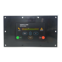
Local Control Key
Four local control are found at the bottom of the control
panel
[Hand On] enables control of the frequency converter via
the LCP. [Hand on] also starts the motor, and it is now
possible to enter the motor speed data by means of the
arrow keys. The key can be selected as Enable [1] or
Disable [0] via par. 0-40 [Hand on] key on LCP. External
stop signals activated by means of control signals or a
serial bus will override a “start” command via the LCP.
The following control signals will still be active when
[Hand on] is activated:
[Hand on] – [Off] – [Auto on]
Reset •
Coasting stop inverse •
Reversing •
Set-up select bit 0-
Set-up select bit 1 •
Stop command from serial communication •
Quick stop •
DC brake
[Off] stops the connected motor. The key can be
selected as Enable [1] or Disable [0] via par. 0-41 [Off]
key on LCP. If no external stop function is selected and
the [Off] key is inactive the motor can be stopped by
disconnecting the voltage.
[Auto On] enables the frequency converter to be
controlled via the control terminals and/or serial
communication. When a start signal is applied on the
control terminals and/or the bus, the frequency converter
will start. The key can be selected as Enable [1] or
Disable [0] via par. 0-42 [Auto on] key on LCP.
An active HAND-OFF-AUTO signal via the digital
inputs has higher priority than the control keys [Hand on]
– [Auto on].
[Reset] is used for resetting the frequency converter after
an alarm (trip). It can be selected as Enable [1] or
Disable [0] via par. 0-43 Reset Keys on LCP.
The parameter shortcut can be carried out by holding
down the [Main Menu] key for 3 seconds. The parameter
shortcut allows direct access to any parameter.
Display Mode
In normal operation, up to 5 different operating variables
can be indicated continuously in the middle section: 1.1,
1.2, and 1.3 as well as 2 and 3.
Display Mode - Selection of Read-Outs
It is possible to toggle between three status readout
screens by pressing the [Status] key. Operating variables
with different formatting are shown in each status screen
- see below.
The table shows the measurements you can link to each
of the operating variables. Define the links via par. 0-20,
0-21, 0-22, 0-23, and 0-24.
Each readout parameter selected in par. 0-20 to par. 0-
24 has its own scale and digits after a possible decimal
point. By larger numeric value of a parameter fewer digits
are displayed after the decimal point. Ex.: Current
readout 5.25 A; 15.2 A 105 A.
Operating Variable: Unit:

 Loading...
