Installation and programming manual
Technical description 15
Chapter 4
Technical description
4.1 Control panel
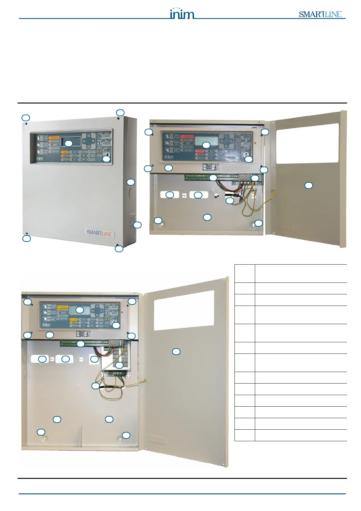
Figure 4 - External and internal parts of the SmartLine020
Figure 5 - Inside the SmartLine036
[A] Frontplate with display, keys
and signalling LEDs
[B] Slot for level 2 access key
[C] Frontplate
[D] Securing screws for the front
cover
[E] Cable entries (located on all
sides of the enclosure)
[F] Data label
[G] Plastic support for front panel
and motherboard mounting
[H] Plastic support anchor screw
[I] About the motherboard
[J] Power supply module
[K] Backup battery housing
[L] Cable entry
[M] Anchor screw hole

 Loading...


