Installation and programming manual
Installation instructions 35
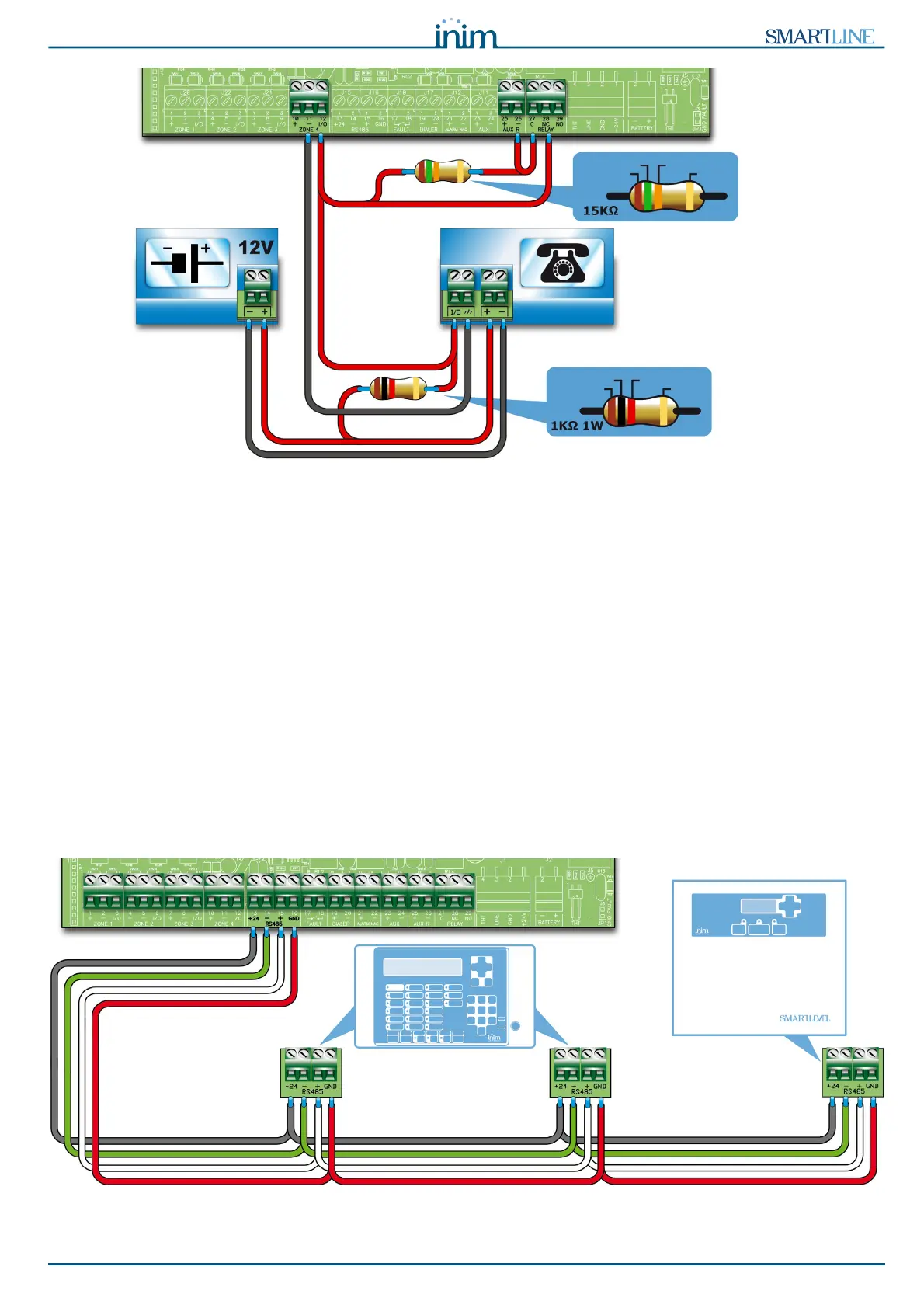
Figure 24 - Connecting the dialler
6.7.1 Wiring
1. Connect the dialler to terminals - and I/0 of zone 4 of the control panel.
2. Add a 1 k1W resistor to the dialler between the activation terminal and the + terminal.
This resistor will monitor the integrity of the connection between the panel and the dialler and will
signal promptly any short-circuits or interruptions.
3. Add a 15 k resistor to the control panel between the zone 4 terminals and the AUX R and
RELAY,terminals, as shown in the figure.
4. Access the SmartLeague software, go to “SmartLine control panel/Other options”, select “Output to
fault warning routing equipment”.
6.8 Connecting the RS485 BUS
The RS485 BUS terminals accept up to 4 SmartLetUSee/LCD-Lite repeaters (remote information points,
generally located in the entrance areas of the protected building) and 2 SmartLevel power stations.
The devices must be connected in parallel. The control panel communicates with devices be means of a
highly noise-immune digital protocol.
Figure 25 - Connecting the RS485 BUS
DIALER
POWER-SUPPLY
BROWN
GREEN ORANGE
GOLD
BROWN
BLACK RED
GOLD
REPEATERS
SmartLetUSee/LCD-Lite
POWER SUPPLY
STATION
SmartLevel