Installation and programming manual
Installation instructions 39
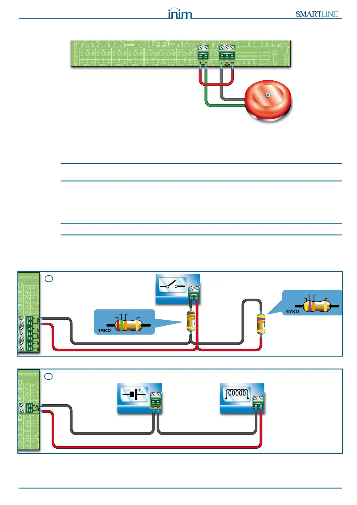
6.13 Connecting RELAY output
Figure 31 - Connecting RELAY output
The RELAY output provides a dry contact that can switch 1A 30V loads. At default the relay is configured to
activate in the event of an alarm but can be configured to activate in the event of various conditions.
Note:
In order to validate the IMQ-SECURITY SYSTEMS certification, this output should not be used as a type C, E
or J output (EN 54-1), and must not be used to command Fire-alarm or Fault transmission devices.
6.13.1 Wiring
Use NON-shielded cable. The wire section should be compatible with the wire length and load connected to
the output.
Note:
The relay contacts on the electronic are suitable for SELV circuitry only.
6.14 Connecting the Extinguishant module
(optional system enhancement tool)
YELLOW
VIOLET ORANGE
GOLD
BROWN
GREEN ORANGE
GOLD
A
POWER SUPPLY 24V
Gas release
electrovalve
B