Installation and programming manual
Powering up and configuring the system 45
Note:
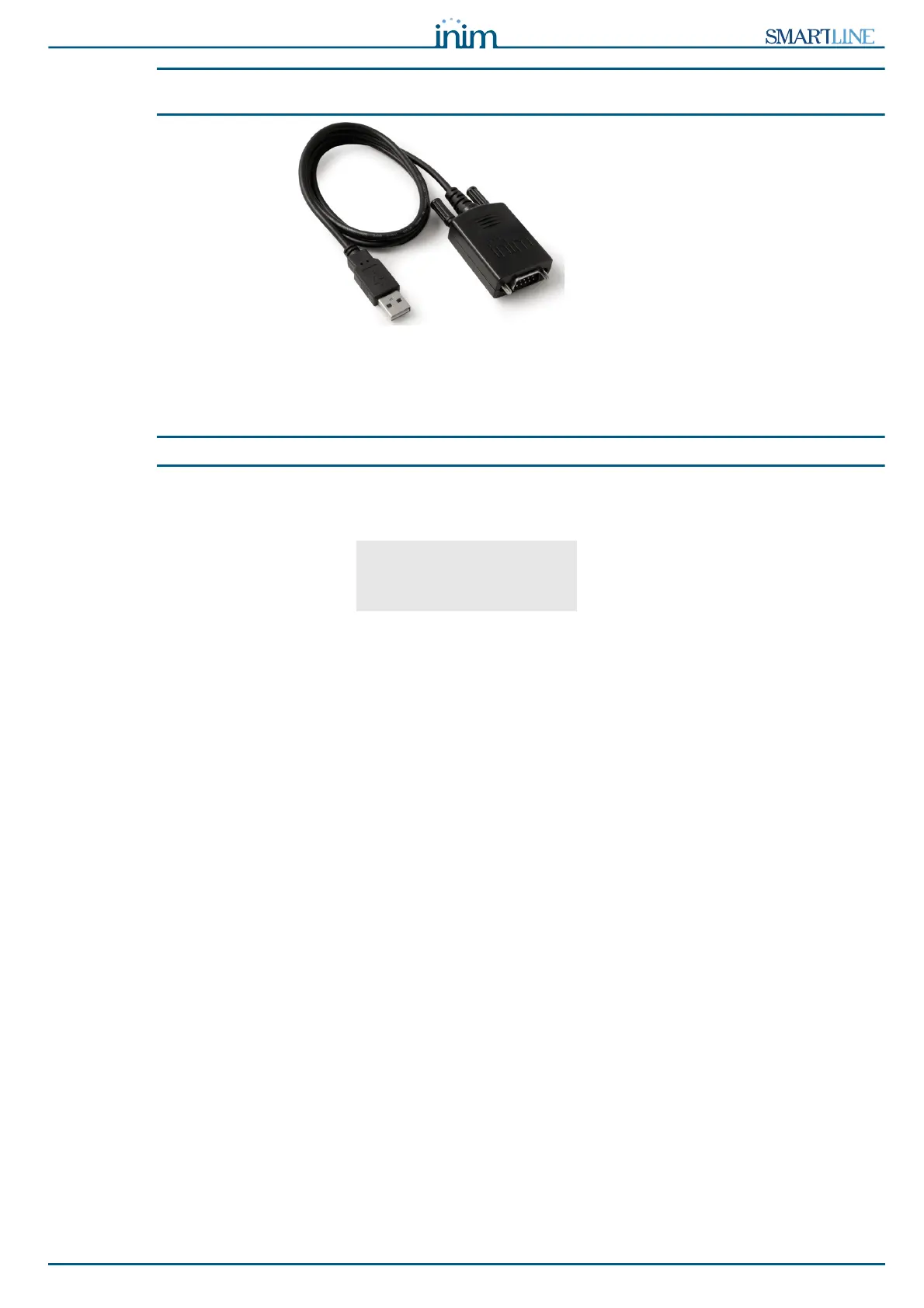
The RS232 link can be ordered separately.
If your PC does not have a RS232 port but has a USB, use an RS232-USB adapter.
7.3 Powering up the system
1. Connect the connection wire between the two batteries and the batteries to the proper connector of the
power-supply module (refer to paragraph 6.16 - Connecting the batteries).
Attention:
Be sure that connector polarity is correct.
The panel will take several seconds to stabilize, startup will be indicated by an intermittent audible signal
and the “
Resetting”.
Figure 35 - Reset signalling
Full panel reset will be indicated by:
- The On status of the green LED (Figure 8 - Frontplate, [S]) indicates that the panel is operating.
- The CPU LED (Figure 8 - Frontplate, [P]) will blink to indicate that the board is initializing.
- If you do not carry out the successive step (connection to the mains power source) within 2 minutes,
the FAULT LED (Figure 8 - Frontplate, [D1]) will go On and the “
Mains Fault” message will appear on
the display.
2. Power up the panel from the mains.
In the event of restoral of a Mains fault; the FAULT LED will blink to indicate that the event has been
saved to the memory.
3. If the fault persists, check all wiring sections thoroughly. See Chapter 16 - Diagnostics and fault
solutions.
4. Once all faults have been cleared, turn the key in the keyswitch (access Level 2) and press the RESET
button (Figure 8 - Frontplate, [D]).
After Reset operations, all the LEDs should go OFF, with the exception of the green ON LED (Figure 8 -
Frontplate, [S]).
The display will show “
Panel working” message.
5. Press any key to access the main menu. Using the cursor key select the second option on the “
Test
LEDs
” menu. Press and hold the Ok key and check that all the LEDs go On.
Control panel
In service
01/01/18 18:23