28 Installation instructions
Conventional fire detection control panel
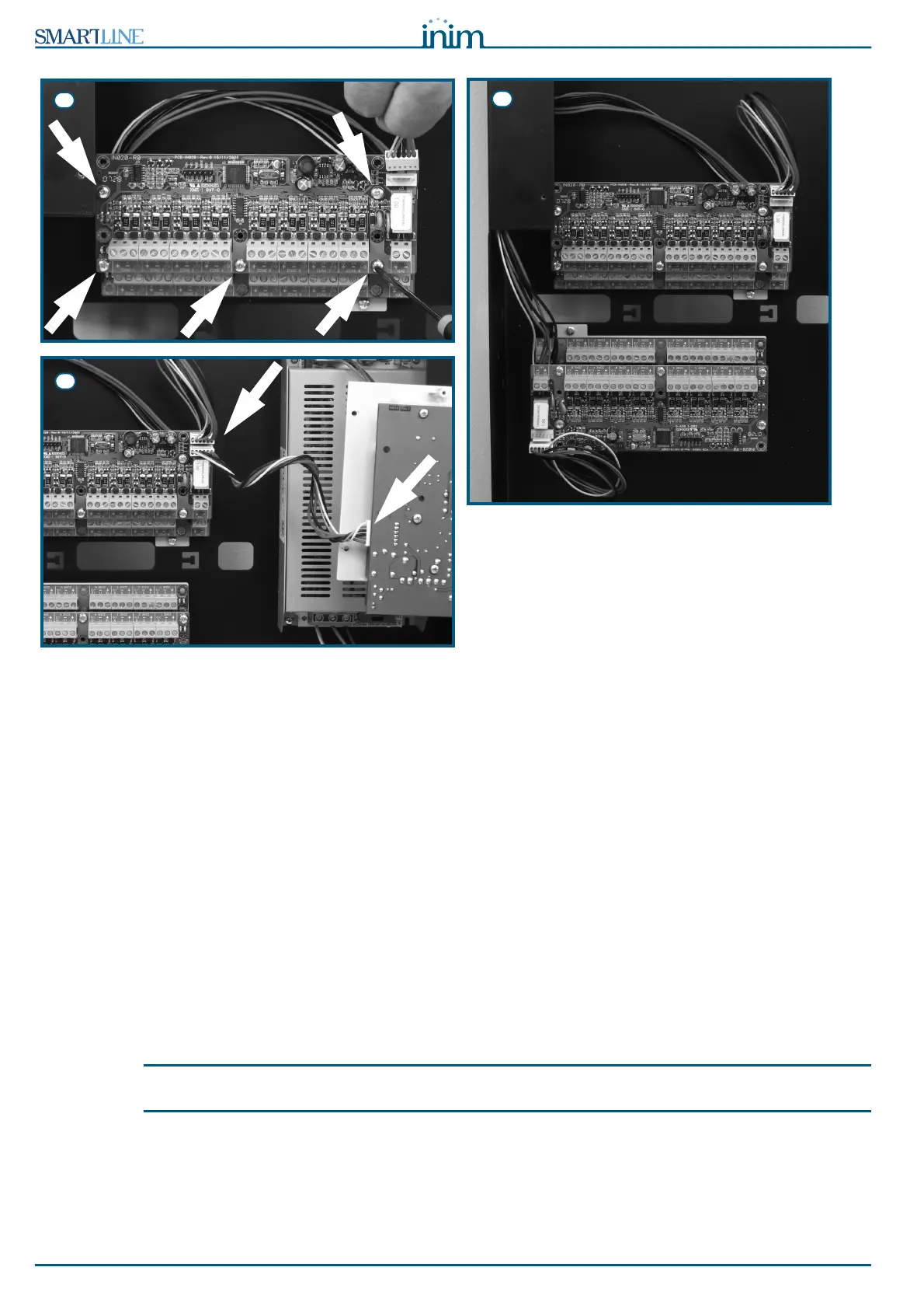
Figure 12 - Mounting the expansion board - 2
1. Remove the four screws and detach the frontplate of the metal enclosure.
2. Remove the four screws and detach the plastic support.
3. Attach the expansion board to the anchor plate, use the metal spacers if you are installing two boards
(Figure 11 - [A]). Take care to use the mounting holes indicated by the arrows in the photograph.
4. Attach the plate with the board to the back of the metal enclosure (Figure 11 - [B]).
5. Using the connection wire, connect the board to the motherboard and to the successive board (Figure
11 - [C]).
6. Locate the second expansion board on the metal spacers (Figure 12 - [D]).
7. Using the connection wire, connect the board to the previous and successive boards.
8. Mount the third and fourth boards to another anchor plate and connect them together.
9. Attach the second anchor plate to the backplate of the enclosure.
10. Connect the third board to the second (Figure 12 - [E]).
11. Using the respective connector, connect the first board to the control panel motherboard (Figure 12 -
[F]).
12. Replace the plastic holder and close the control panel cabinet.
Note:
In order to allow the control panel to manage the expansion board, you must include it in the configuration.
Refer to the Programming section for details.
6.2 Mounting the SmartLAN/485 Ethernet board (accessory item)
The SmartLAN/485 allows you to program the control panel parameters from remote locations by means of
the SmartLeague software via LAN/the Internet. Additionally, the SmartLAN/485 is capable of sending a
UDP packet (event description report) to a configurable IP address each time the control panel registers an
event.