Installation and programming manual
Installation instructions 29
As a result of this feature, the fire-detection panel can be supervised through INIM's custom software
(SmartLook), or integrated into any supervisory software.
For further details and for the installation procedure, refer to the manual provided with the board.
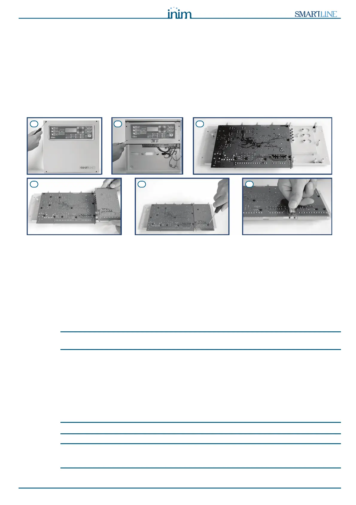
6.3 Mounting the SmartLetLoose/ONE extinguishant board (accessory item)
The extinguishant board comes in a separate cardboard box. Together with the extinguishant board
(IN015), you will find a plastic bag containing:
• Jumper for connection between the extinguishant board and the SmartLine motherboard
•Screws
• EOL resistors and diodes
Figure 13 - Mounting the extinguishant board
1. Remove the four screws and detach the frontplate of the metal enclosure.
2. Remove the four screws and detach the plastic support.
3. Rotate the SmartLine motherboard as shown in the figure.
4. Position the extinguishant board in its housing.
5. Using the screws (included), secure the extinguishant board in place.
6. Connect pins J13 of the SmartLine motherboard (paragraph 4.2 - [P]) to the respective pins J2 on the
extinguishant board.
7. Move the SmartLine motherboard back to its original position.
8. Replace the plastic support.
Note:
In order to allow the control panel to manage the connected extinguishant board, you must include it in the
configuration. Refer to the Programming section for details.
6.4 Wall mounting
6.4.1 Control panel
1. Pull the wires through the wire entry and in such a way that they do not get in way of the installation
procedure.
2. Prepare the wall for the four 8mm anchor screws (stop screws) which must be positioned in
correspondence with the holes on the backplate of the metal enclosure (paragraph 4.1 - [M]).
Danger:
Take care not to drill in the vicinity of electrical wiring, heating ducts and plumbing.
Note:
Choose anchor screws which are capable of supporting 20kg and which are suitable for the characteristics of
the wall.
Ask for professional advice with regard to the best type of anchor screw for the wall concerned.
3. Using the 4 anchor screws, attach the enclosure securely to the wall.