Installation and programming manual
Installation instructions 41
6.14.2 Outputs
6.15 Connecting the mains power source
The power system of the SmartLine control panel is EN54-4 compliant.
Danger:
DO NOT power up the system with a non-compliant voltage.
1. Connect the mains power supply to the terminals on the power-supply module (Figure 7 - Switching
power supply, [A] and Figure 33 - Earthing system, [A]).
For a safety standards compliant system, the Line must be connected to terminal “L”, the Neutral
conductor to terminal “N”.
This panel must be connected to a separate line on the Electrical Switchboard (Mains power supply).
The line must be protected by a sectioning device which complies with local safety regulations, fire
codes, laws and bylaws in force.
Note:
As a further safety measure, the electrical system of the building must be protected against overload and
short-circuit.
Note:
The ends of wires must not be soft soldered in points where they are subject to clamping.
• Primary power source: 230V (-15%/+ 10%) 50/60Hz
• Max. current draw SmartLine020 control panel: 0.5 A
• Max. current draw SmartLine036 control panel: 1.1 A
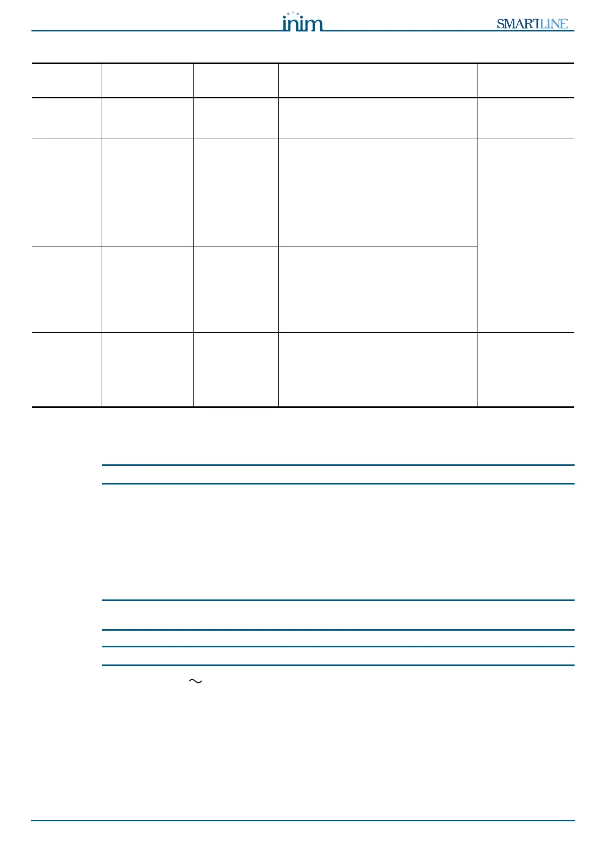
Terminal
Device/s to
connect
Output Type Note Wiring Diagram
VALVE Electrovalve for
gas release.
Supervised Figure 32 -
Extinguishant
module/B
PRE-EXT Audible and Visual
signalling devices
Supervised The signalling devices activate as soon as
the detectors sense fire conditions that
require gas extinguishant intervention.
This will allow building occupants to
evacuate the building before the gas
extinguishant is released. The delay
between the activation of alarm signalling
devices and the release of the gas
extinguishant is customizable.
Figure 32 -
Extinguishant
module/C
47K Balancing
RELEASED “Extinguishant
Gas release”
signalling devices
Supervised There are two activation modes:
- activation on confirmation of
Extinguishant Gas release;
- simultaneous activation with the
electrovalve output. This mode requires
gas detectors in the protected
environment.
R Remote LED that
signals the
deployment of the
STOP
extinguishant-
system button.
Open Collector
(non-
supervised)
Activates (closes to GND) in the event of
activation of the STOP EXT input (max
100 mA).
Figure 32 -
Extinguishant
module/D