40 Installation instructions
Conventional fire detection control panel
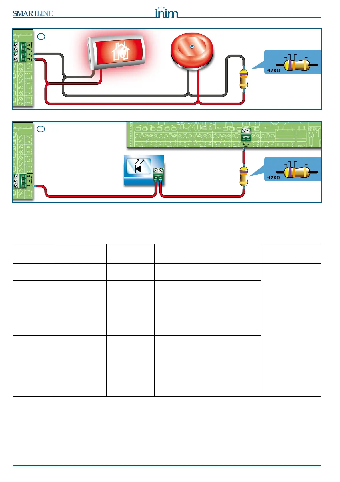
Figure 32 - Extinguishant module
6.14.1 Inputs
Terminal
Device to be
connected
Input Type Note Wiring Diagram
MAN-EXT Extinction system
Start button
Supervised. Up to 20 devices can be connected to
this input.
Figure 32 -
Extinguishant
module/A
47K = Standby
15K = Active
STOP-EXT Button to stop the
extinction-system
manually
Supervised. The STOP extinguishant-system button
should always be located near to the
protected area. This will allow any
persons present during the release of
extinguishant gas to stop the process
and evacuate the area unharmed. Up
to 20 devices can be connected to this
input.
PRESS Gas extinguishant
pressure switch.
Supervised. The pressure switch has two functions:
- Under normal operating conditions, it
monitors the pressure of the Gas
extinguishant. If the pressure drops
spontaneously below the pre-set value,
it will generate a fault signal.
- After an 'Extinction' command, it
confirms that the command has been
executed.
YELLOW
VIOLET ORANGE
GOLD
STOP-
EXTINCTION
signalling LED
SmartLine
control panel
D
 Loading...


