Installation and programming manual
Installation instructions 31
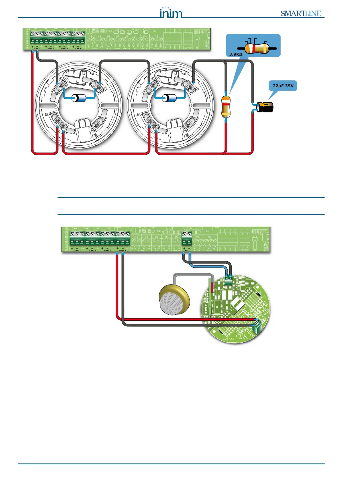
Figure 16 - Wiring for detection with missing detectors
If detectors are wired as per the diagram and the “Det.Missing” option is enabled, the control panel will
generate a fault signal when a detector is removed from its base and at the same time will be able to
receive alarm signals from other detectors connected downstream.
Attention:
If you enable the “Det.Missing” option for a zone that is not wired as illustrated in the figure,
the control panel will signal fault only.
Figure 17 - Connecting gas detectors to the detection line
If the wiring is completed as per the diagram, it will be possible to interface the control panel with a gas
line (line configured as a GAS line; refer to the zone programming section).
The example shows a gas detector from “industrial” series, “-ASC” version.