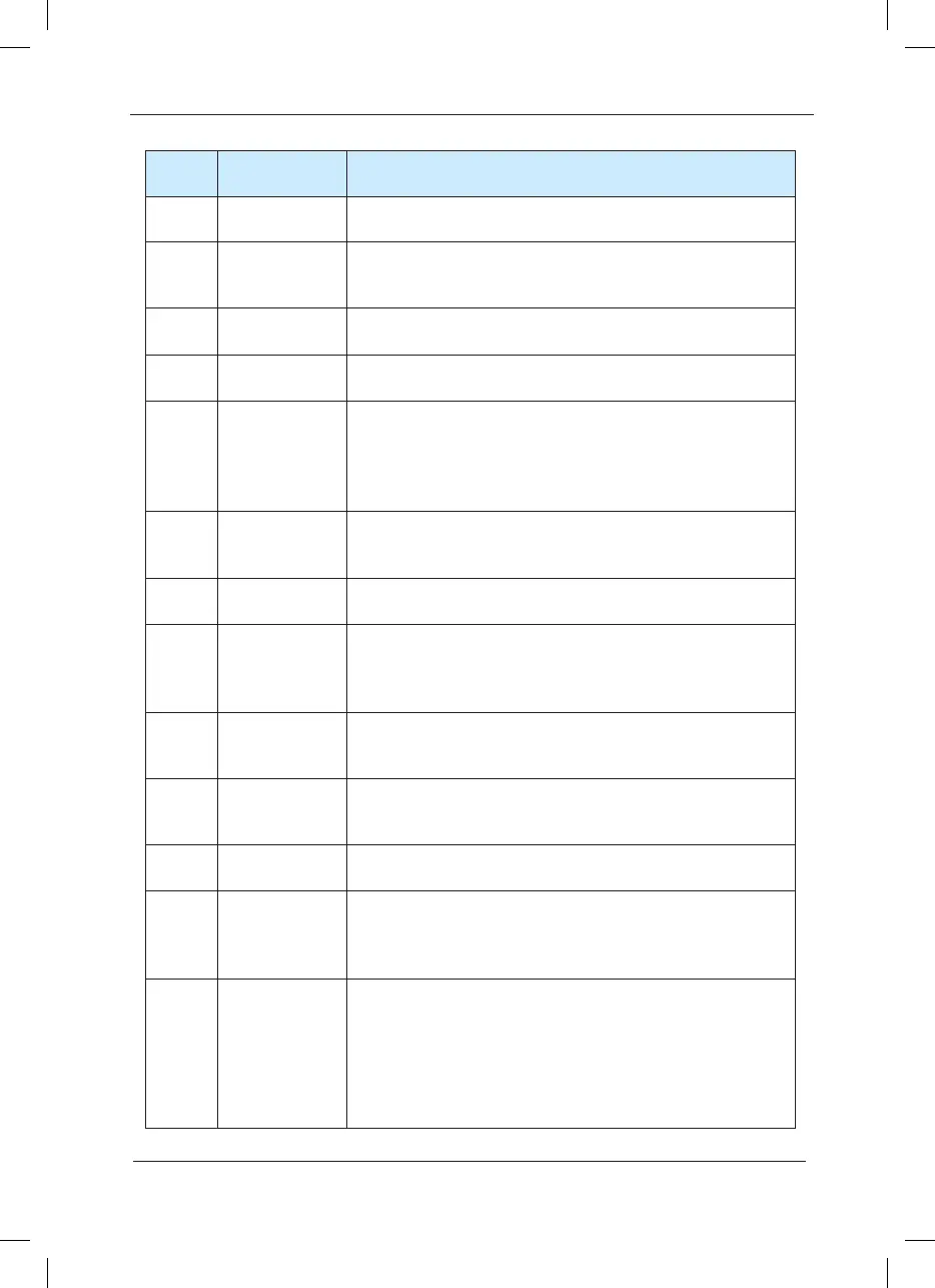
Setup
value
Function Description
2 Fault output When the inverter is faulty, it outputs ON signal.
3
Frequenc-y
level detection
FDT arrival
Please refer to F8-19 and F8-20 for details.
4
Frequenc-y
arrival
Please refer to F8-21 for details.
5
in zero speed
operation
When the inverter output frequency is less than the start
frequency, it outputs ON signal.
6
Motor overload
pre-warning
Judgment will be made according to the pre-warning parameter
value before the motor electronic thermal protection is enabled.
If it exceeds the pre-warning value, it will output ON signal.
Motor overload parameters are set in F9-00 to F9-02.
7
Inverter
overload pre-
warni-ng
After it is found that the inverter is overloaded, pre-warning will
be invoked 10 seconds before the occurrence of protection. And
ON signal will be output.
8
Setup counting
pulse arrival
When the counting value reaches the setup value of FB-08, it
outputs ON signal.
9
Designat-ed
counting pulse
arrival
When the counting value reaches the setup value of FB-09, it
outputs ON signal. Refer to Group B function description for the
counting function.
10 Length arrival
When the measured actual length exceeds the setup value of
FB-05, it outputs ON signal.
11
PLC circulation
complete-on
When the simple PLC has been running for one cycle, it outputs
a pulse signal with width of 250ms.
12 Run time arrival
When the accumulated running time of the inverter exceeds the
setup time F8-17, it outputs ON signal.
13
Frequenc-y
limiting
When the setup frequency exceeds the frequency upper limit
and frequency lower limit, and the output frequency of the
inverter reaches the frequency upper limit and frequency lower
limit, it outputs ON signal.
14 Torque limiting
When the torque limiting function is enabled, the stall protection
function is automatically enabled and the output frequency
is automatically changed. Meanwhile, it outputs ON signal,
indicating that it is outputting torque limit. This output signal can
be used to reduce load or display overload status signal on the
monitoring device.
 Loading...
