F5-06
FMR output selection (Pulse
output terminal)
Factory default
value
0
F5-07
A01 output selection (Analog
output terminal 1)
Factory default
value
0
F5-08
A02 output selection (Analog
output terminal 2)
Factory default
value
1
The standard output of analog output (zero offset is 0 and gain is 1) is 0mA to 20mA (or 0v TO
10V), and the output range of FMP is between 0Hz and setup value of F5-09.
The corresponding value range that it indicates is shown in the table below:
Setup
value
Function Description
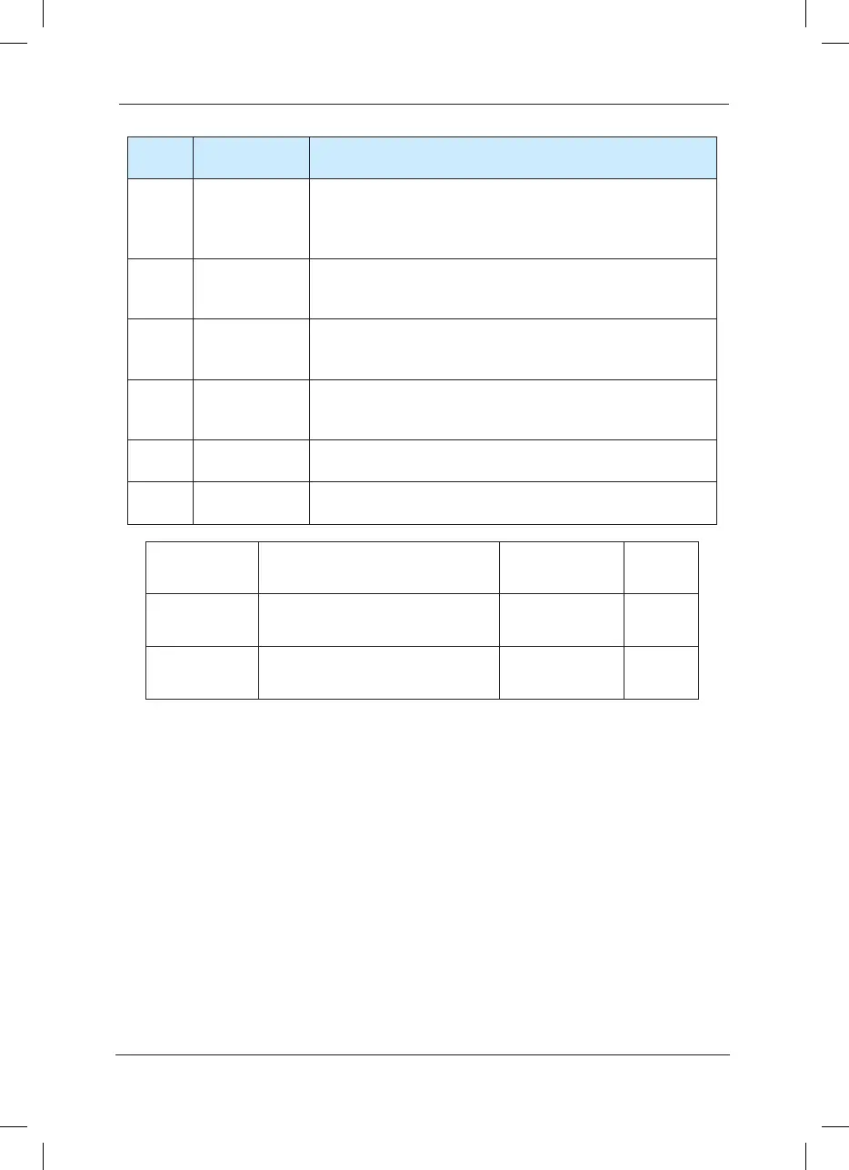
15
Ready for
running
When the main circuit and control circuit power supply are
connected, the inverter protection function is inactive, and the
inverter is in running status, it output ON signal.
16 AI1>AI2
When the analog input AI1 value is higher than AI2 value, it
outputs ON signal.
17
Frequency
upper limit
arrival
When the running frequency reaches frequency upper limit, it
outputs ON signal.
18
Frequency
lower limit
arrival
When the running frequency reaches frequency lower limit, it
outputs ON signal.
19
Under voltage
status output
When the inverter is in under voltage status, it outputs ON
signal.
20
Communication
setup
Refer to the communication protocol for relevant descriptions.
 Loading...
