It is used to record the fault types of inverter for the most recent three times: 0 indicates no
fault, while 1 to 24 indicates ERR01 to ERR24. Refer to Chapter 7 for details.
F9-17
Frequency upon
fault
Display the frequency upon fault for the most recent one time.
F9-18
Curr e nt upon
fault
Display the current upon fault for the most recent one time.
F9-19
B u s v o l t a g e
upon fault Display the bus voltage upon fault for the most recent one time.
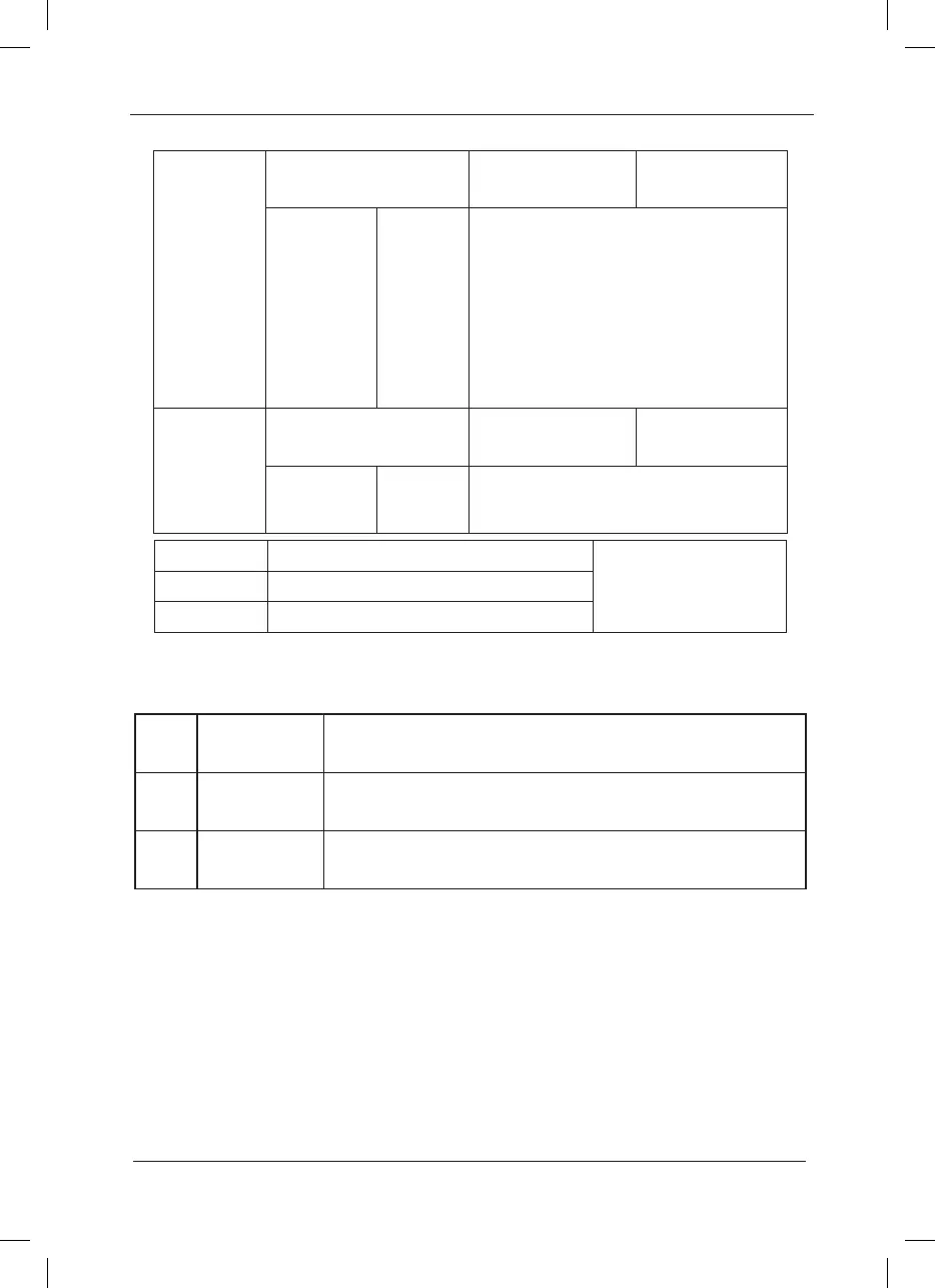
F9-12
Input phase failure
protection selection
Factory default
value
1
Setup range
0:Inactive
1:Active
Select whether to provide protection for
input phase failure. Only the MD series
inverter of G model with over 18.5kW can
have input phase loss protection function,
and the P model with 18.5kW has not
such function no matter whether F9-10 is
set to 0 or 1.
F9-13
Output phase failure
protection selection
Factory default
value
1
Setup range
0:Inactive
1:Active
Select whether to provide protection for
output phase failure.
F9-14 First fault type
0
~
24F9-15 Second fault type
F9-16 Most recent fault type
 Loading...
