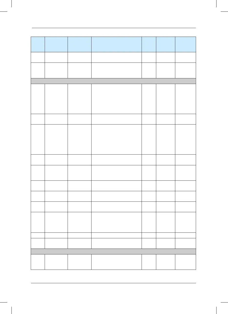
Function
code
Name LED display Set range
Minim-
um unit
Factory
default
value
Modication
description
F9-20
Input terminal
upon fault
Input terminal
upon fault
- - - ●
F9-21
Output
terminal upon
fault
Output
terminal upon
fault
- - - ●
Group FA PID Function
FA-00
PID setup
source
PID setup
source
0: FA-01
1: AI1
2: AI2
3: AI3
4: PULSE setup (DI5)
5: Communication setup
1 0
☆
FA-01
PID keyboard
setup
PID setup 0.0%
~
100.0% 0.1 50.0%
☆
FA-02
PID feedback
source
PID feedback
source
0: AI1
1: AI2
2: AI3
3: AI1-AI2
4: PULSE setup (DI5)
5: Communication setup
1 0
☆
FA-03
PID action
direction
PID action
direction
0: Positive action
1: Reverse action
1 0
☆
FA-04
PID setup
feedback
range
PID range 0
~
65535 1 1000
☆
FA-05
Proportional
gain P
Proportional
gain P
0
.
0
~
100
.
0 0
.
1 20
.
0
☆
FA-06
Integration
time l
Integration
time l
0.01s
~
10.00s 0.01s 2.00s
☆
FA-07
Differential
time D
Differential
time D
0.000s
~
10.000s 0.01s 0.00s
☆
FA-08
Cutoff
frequency of
PID reverse
rotation
Cutoff
frequency
of reverse
rotation
0.00 ~ maximum frequency 0.01Hz 2
.
00Hz
☆
FA-09 Deviation limit Deviation limit 0.0%
~
100.0% 0.1% 0.0%
☆
FA-10
Differential
amplitude
Differential
amplitude
0%
~
100% 1% 5%
☆
Group FB Swing Frequency, Fixed Length and Count
FB-00
Swing setup
mode
Swing setup
mode
0: Relative to the central
frequency
1: Relative to maximum frequency
0
.
01 0
.
00
☆
 Loading...
