6 Parameter Description
-
237
-
5 4
3
2
1
SPI
communication
quality of the
drive unit
SPI
communication
quality of the
power supply
unit
CAN2
communication
quality
MOD
communication
instruction
CAN1
communication
quality
0 High 0 High 0 High 0 High 0 High
9 Interrupted 9 Interrupted 9 Interrupted 9 Interrupted 9 Interrupted
0 to 9 indicate the communication quality, where a larger value indicates stronger
interference and lower communication quality.
Function
Code
Name Setting Range Default Unit Property
FA-26 Input state 1 0 to 65535 0
FA-27 Input state 2 0 to 65535 0
FA-28 Input state 3 0 to 65535 0
FA-29 Input state 4 0 to 65535 0
FA-30 Input state 5 0 to 65535 0
FA-31 Output state 1 0 to 65535 0
FA-32 Output state 2 0 to 65535 0
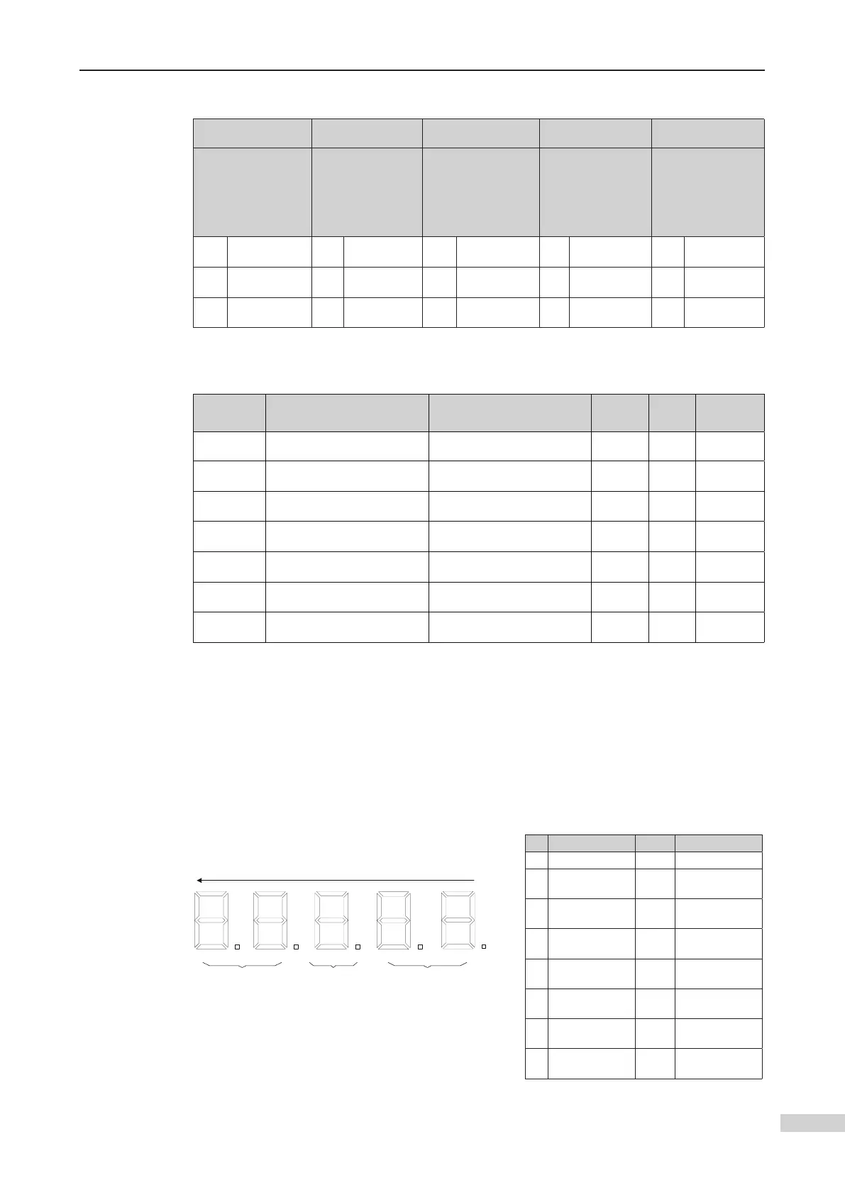
FA-26 to FA-32 display the system input and output states.
Description of input state 1 display of FA-26
to left. 5 and 4 indicate an input or output terminal function. 3 indicates that this
function is enabled (1) or disabled (0). 1 and 2 display the overall state of 16 functions
contained in this parameter using 16-segment LEDs.
No. Signal Number
0 Reserved 8 Inspection signal
1 Up leveling signal 9
Inspection up
signal
2
Down leveling
signal
10
Inspection down
signal
3 Door zone signal 11
Fire emergency
signal
4
Safety circuit
feedback
12 Up limit signal
5
Door lock circuit
feedback
13 Down limit signal
6
RUN contactor
feedback
14 Overload signal
7
Brake contactor
feedback
15 Full-load signal
8
9
10
11
12
13
14
15
5
4 3
2
0
1
2
3
4
5
6
7
1
Present signal No.
State of
present signal
Each segment
indicates a signal
0: Inactive
1: Active
FA-26 input state 1 display
 Loading...