9 Description of Functions and Schemes
-
307
-
Set F
8-
01 to 0
Set F8-00 to 0.
Press ENTER on the
operation panel.
Make the car unloaded
Set F8-00 to N.
Press ENTER on the
operation panel.
End
Put N% load in the car
F8-06 and F8-07 respectively record the obtained no-load and full-load data after the
load cell auto-tuning is successful. You can also monitor the current load condition in
the car by viewing F8-05. When the current load exceeds 110% of the rated load, the
system reports overload warning.
◆
Note that F8-05 to F8-07 record the binary data indicating the car load condi-
tion rather than the ratio of actual car data to the rated car load.
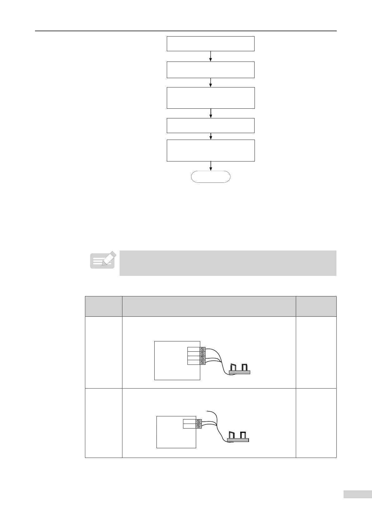
Wiring and parameter setting of digital full-load/overload switches
Type Wiring Diagram
Parameter
Setting
Connected
to CTB
The full-load signal and overload signal must be respectively
connected to X7 and X8.
CN3
X8
X7
P24
Digital load cell
MCTC-CTB-A
Full load
Overload
DC24V
F5-36 = 1
Connected
to MCB
CN9
X23
X24
Digital load cell
MCTC-MCB
24V
Full load
Overload
F5-36 = 0
(CTB analog
input)
 Loading...