2 Installation and Wiring
-
51
-
2 Description of terminals
Main circuit terminal description
No. Name Description
R, S, T
Three-phase power
input terminals
Provide three-phase AC power supply.
+, -
Positive and
negative terminals
of DC bus
Connect the external braking unit and energy feedback
unit for models of 37 kW (F model 45 kW) and above.
+, PB(P)
Terminals for
connecting regen.
resistor
Connect the regen. resistor for models of below 37 kW (F
model 45 kW).
Connect the DC reactor for models of 37 kW (F model 45
kW) and above.
At delivery, the + and P terminals are shorted with the
jumper bar. If you need not connect the DC reactor, do not
remove the jumper bar.
U, V, W
Controller output
terminals
Connecting the three-phase motor
Grounding terminal Grounding terminal
3 Wiring
■
Power input terminals R, S, T
■
The cable connection on the input side of the controller has no phase sequence
requirement.
■
with the local safety regulations and related IEC standards.
■
Use copper conductors of a proper size as power cables according to the
recommended values in
Table 3-2
.
■
conductive plane that are connected to main grounding of the cabinet.
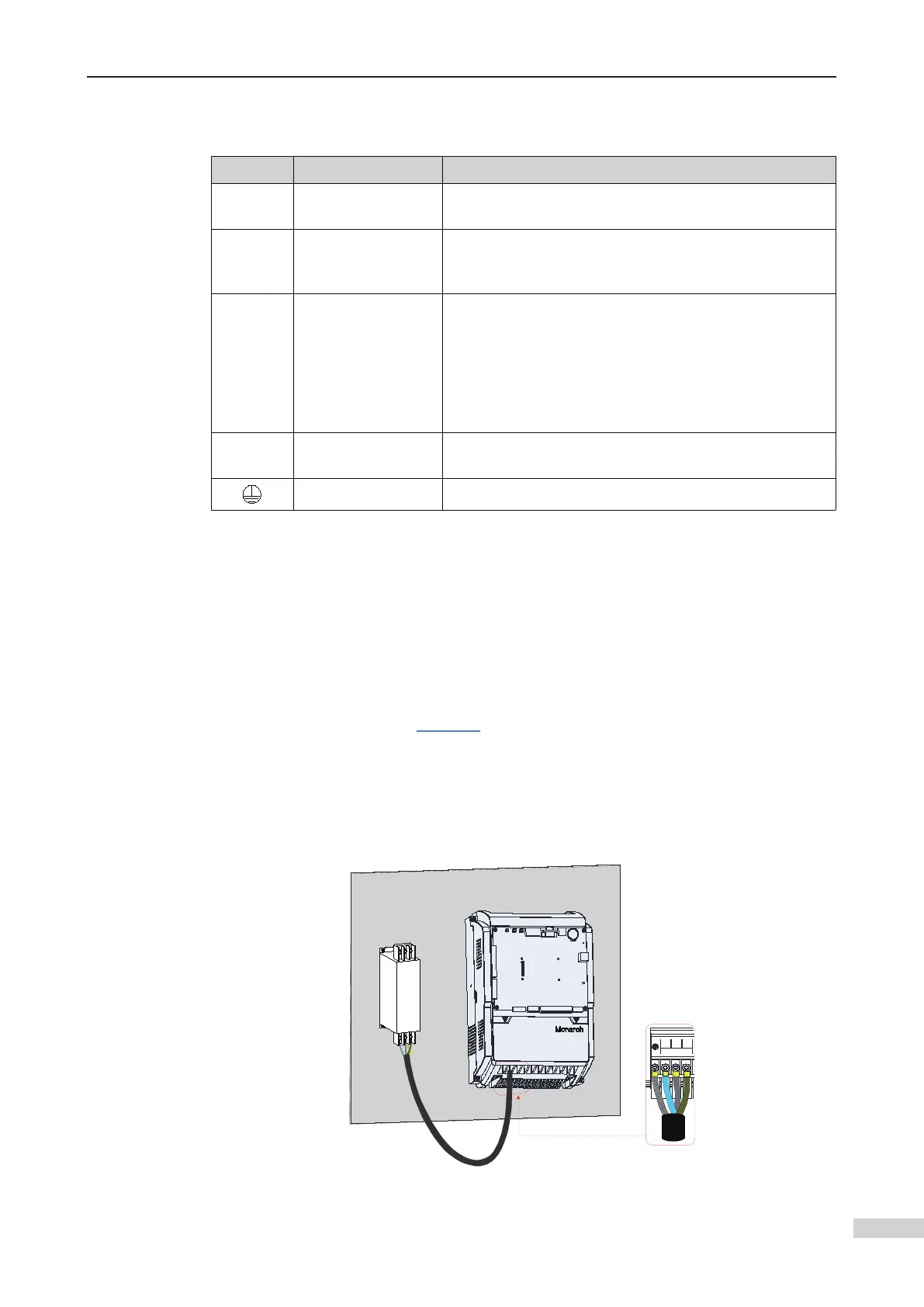
Installation on the conductive plane
 Loading...