- 8 -
1 Servo System Selection
1
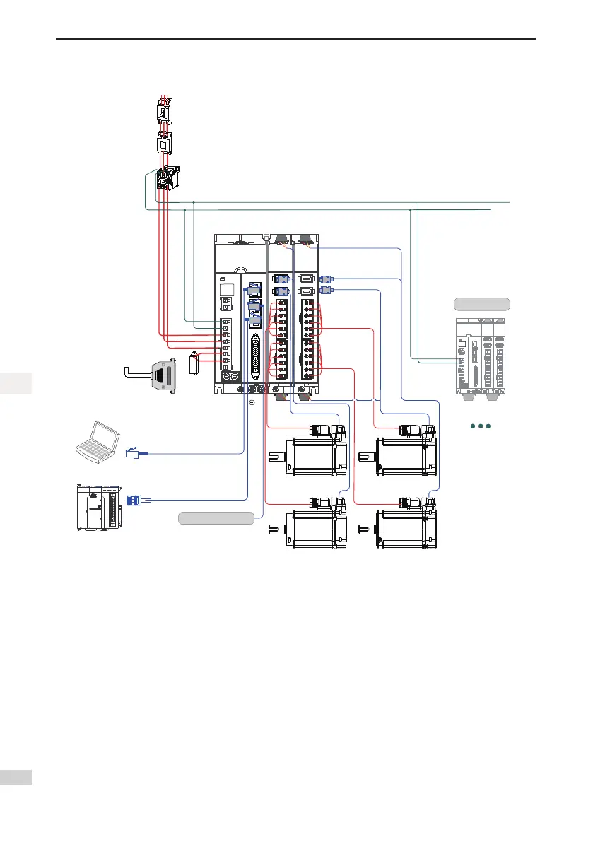
Figure 1-2 Wiring example of three-phase 220 V/380 V system
Circuit breaker for
wiring
Used to protect power
lines by cutting off the
circuit when an
overcurrent
occurs.
Noise filter
Avoid the external
noise from the power
lines by installing a
noise filter.
Electromagnetic
contactor
Turn on/off the
servo motor.
Please install a
surge protection
device (SPD)
before use.
Regenerative
resistor
Terminal P-C
connects to the
external regenerative
resistor if there is
insufficient capacity
for the bus.
Power supply
Three-phase 220 V AC
Servo drive PLC
communication cables
Servo drive multi-device
communication cables
L1C
L2C
L1
L2
L3
P
C
N
L1
C
L2
C
L1
L2
L3
P
C
N
BR+
BR-
PE
U
V
W
BR+
BR-
PE
U
V
W
BR+
BR-
PE
U
V
W
BR+
BR-
PE
U
V
W
*1
3940
2 1
CN
5
CN
3
EtherNET Ether CAT
CN1 RS48
5
C
N
2
C
A
N
CANERR
CANRUN
BF
SF
ERR
RUN
RUN/ STOP
MFK
0 1 2 3 7654
2 765410 3
4 5 6 73210
I
II
CN4
Servo drive input/
output cables
(Equipped by user)
Servo motor
encoder cables
Servo motor encoder cables
Servo motor main circuit cables
Servo motor main circuit cables
Servo drive Ethernet
communication cables
(Support multi-device common
DC bus connection. System
wiring is shown on the left.)
Servo drive
Servo motor
Servo motor
Servo motor
Servo motor
Connect to the next servo drive
Servo motor main
circuit cables
Next servo drive
The servo drive is directly connected to an industrial power supply, with no isolation such as transformers.
Inthiscase,afuseorcircuitbreakermustbeconnectedontheinputpowersupplytopreventcrosselectric
accidentsintheservosystem.Theservodriveisnotconguredwiththebuilt-inprotectivegroundingcircuit.
Connect a residual current device (RCD) against both overload and short-circuit or a specialized RCD com-
bined with protective grounding.
Do not use magnetic contactors for running or stopping the servo motor. As a high-inductance device, the
motor generates instantaneous high voltage, which may damage the contactor.
Pay attention to the power capacity when connecting an external control power supply or 24 V DC, especially
whenthepowersupplyisforpoweringupmultipledrivesorbrakes.Insufcientpowersupplywillleadtoa
lackofthesupplycurrent,thuscausingafailureofthedrivesorbrakes.Thebrakeshallbepoweredupbya
24VDCpowersupply.Thepowermustmatchthemotormodelandmeetsthebrakerequirements.
Observethefollowingprecautionsduringwiring:
1. ProvideableederresistorbetweenterminalPandCwhentheservosystemisunderfeedbackbraking
mode.
2. CN3 is an Ethernet interface, and CN4 and CN5 are for connecting EthnerCAT. CN4 is used to connect
the next slave device, while CN5 is used to connect the master station or previous slave device.

 Loading...


