- 66 -
3 Wiring
3
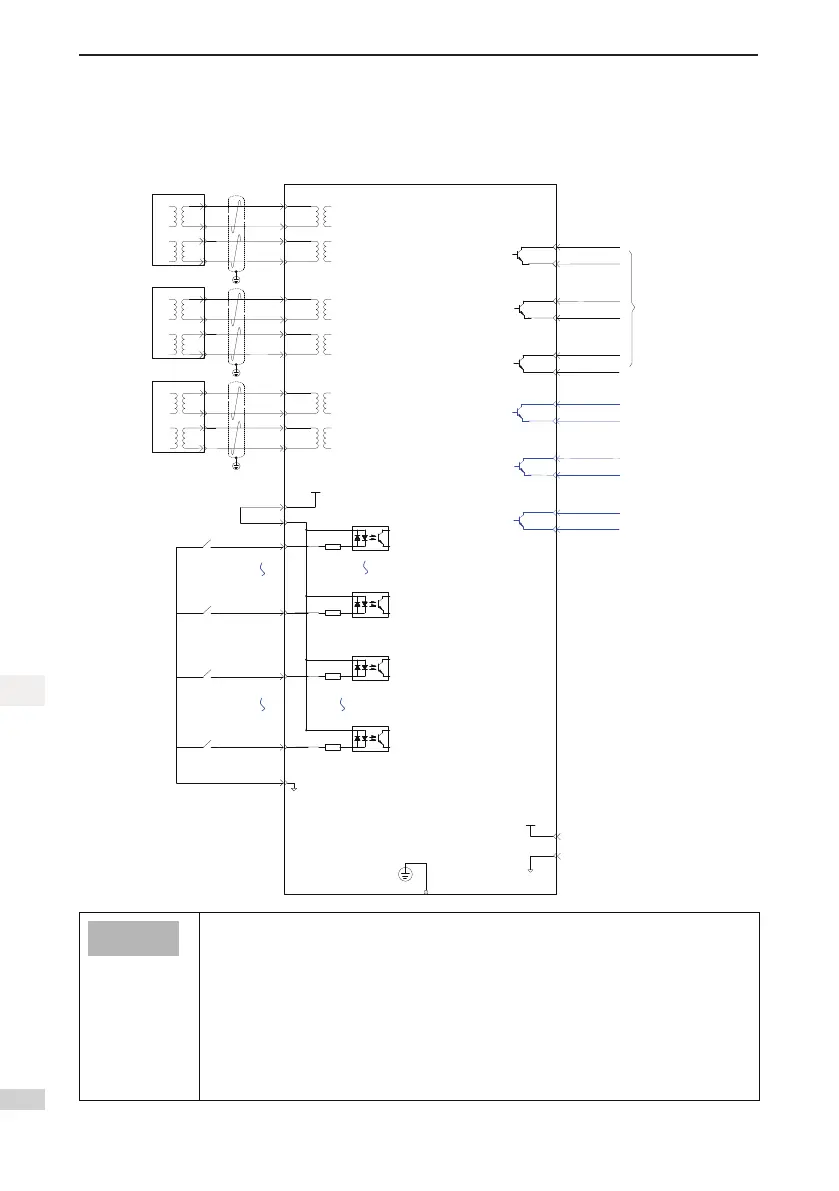
3.10 Overall Wiring
Figure 3-23 Overall wiring diagram
Servo drive
PE shield
connects with
the connector
housing
DO2+
35
36 DO2-
DO1+
33
34
DO1-
DO3+
37
38
DO3-
State
output
Note 4
29
15
GND
+5V
GND
5V
Note 5
DI1
24V
COM+
9
11
17
+24 V
power
supply
DI16
20
DI17
19
DI24
8
COM-
15
Note
1
2.4 kΩ
2.4 kΩ
4.7 kΩ
4.7 kΩ
RX+
3
RX
-
6
TX
+
1
TX-
2
Host
controller
Next slave
station
RX+
3
RX-
6
TX+
1
TX-
2
RX+
3
RX-
6
TX+
1
TX-
2
RX+
3
RX-
6
TX+
1
TX-
2
Note 2
RX+
3
RX-
6
TX+
1
TX-
2
PC
RX+
3
RX-
6
TX+
1
TX-
2
DO5+
41
42 DO5-
DO4+
39
40
DO4-
DO6+
43
44
DO6-
Note 3
High-speed
input
Normal input
● Note1:UseCAT.5Edouble-shieldedcablefornetworkinterfaces.Straight-throughand
crossover Ethernet cables are acceptable.
● Note2:Internal+24Vpowersupply,voltagerange:20Vto28V,maximumworkingcurrent:
200 mA.
● Note3:AsDI1–DI16arehigh-speedDIs,pleaseusethemaccordingtothefunctions.Ifthey
areusedinlowspeedcircumstances,theinternallteringparametersmaybeincreased
according to the function code to enhance the anti-interference capacity.
● Note4:CustomersneedtopreparethepowersupplyforDOs,withvoltagerangingfrom5V
to 24 V. The DO terminals support 30 V DC voltage and 50 mA current to the maximum.
● Note5:Theinternal+5Vpowersupplysupportsamaximumof200mAoutputcurrent.

 Loading...


