- 37 -
3 Wiring
3
3.1.3 RecommendedModelsandSpecicationsoftheMainCircuitCables
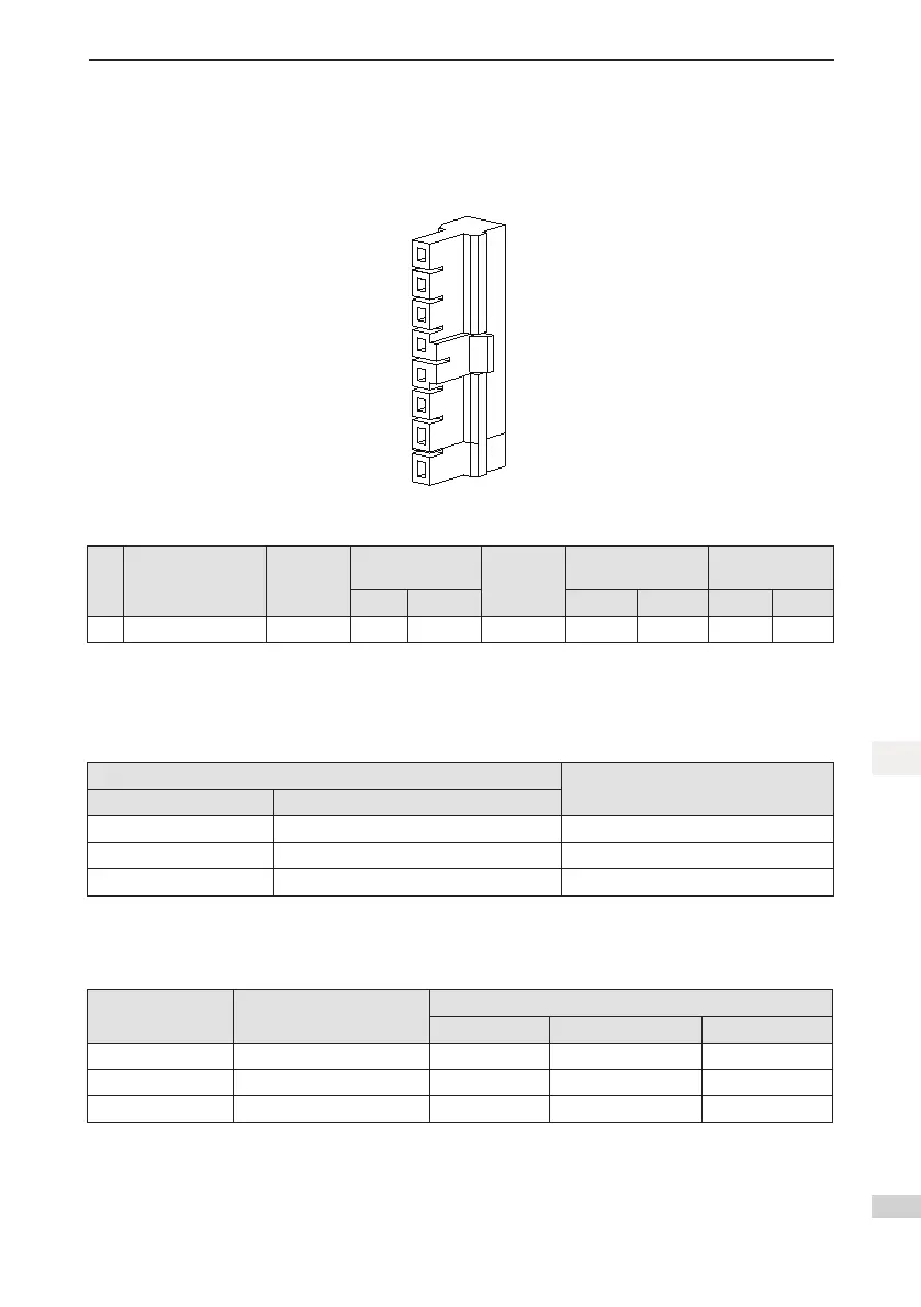
Thegurebelowshowstheconnectorsofthemaincircuitcables.Theseconnectorsaccompanythecom-
plete drive (model to be complemented at the time of producing in batches).
Figure 3-4 Figure of the main circuit cable connectors
Table 3-2 Recommended main circuit cable and cable model for SV820N series servo drive
No.
Drive Model
Single-phase 220 V
Rated
Input
Current (A)
Recommended
Input Power Cable
Rated
Output
Current (A)
Recommended
Output Power Cable
Recommended
Grounding Cable
mm
2
AWG mm
2
AWG mm
2
AWG
1 SV820N1S2C2C 4.6 2 x 0.5 20 2.80 2 x 0.5 20 0.50 20
For other requirements on the main circuit cables, refer to "3.1.5 Precautions for Main Circuit Wiring" for
details.
Thefollowingtabledescribesthemaincircuitcables:
Table 3-3 Recommended main circuit cables
Cable Type
Allowed Temperature (
℃
)
Model Name
PVC General PVC cable -
IV PVC cable rated 600 V 60
HIV Special heat resistant PVC cable 75
The following table describes the relation between the 3-cable diameter and current. The actual value shall
not exceed the value in the table.
Table 3-4 3-cablespecications
AWGSpecication
Nominal Sectional Area
(mm²)
Allowable Current in Different Ambient Temperatures (A)
30
℃
40
℃
50
℃
20 0.519 8 7 6
19 0.653 9 8 7
18 0.823 13 11 9

 Loading...


