- 58 -
3 Wiring
3
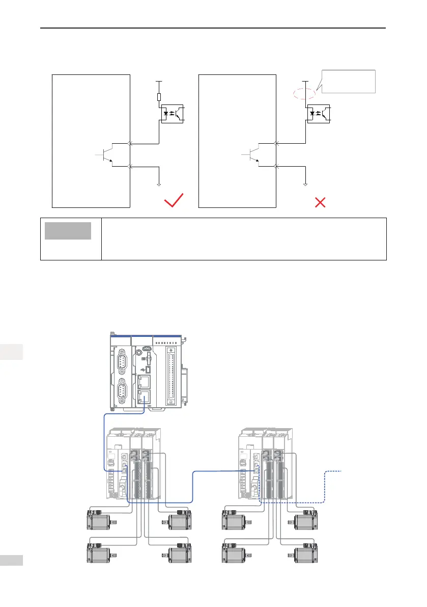
When the host controller provides optocoupler input:
Servo drive
External
5−24 V DC
DO1-
DO1+
Optocoupler
External 0 V
34
33
Servo Drive
External
5−24 V DC
DO1-
DO1+
Optocoupler
External 0 V
The current limiting
resistor is not
connected
34
33
The maximum allowable voltage and current of the optocoupler output circuit inside the servo
driveareasfollows:
● Maximumvoltage:30VDC
● Maximumcurrent:DC50mA
3.6 Wiring to Communication Signal Connectors (CN4/CN5)
3.6.1 Wiring Diagram
Figure 3-14 Networktopologyofcommunicationgroup
AM600
MFK
RUN/
STOP
3940
2 1
CN5
CN1 RS485 CN2 CAN
CN3 Ethernet CN4 EtherCAT
CANERR
CANRUN
BF
SF
ERR
RUN
0
1 2 3
765
4
2 76
541
0 3
4 5
6 73
210
I
II
SV820N SV820N
.

 Loading...


