- 59 -
3 Wiring
3
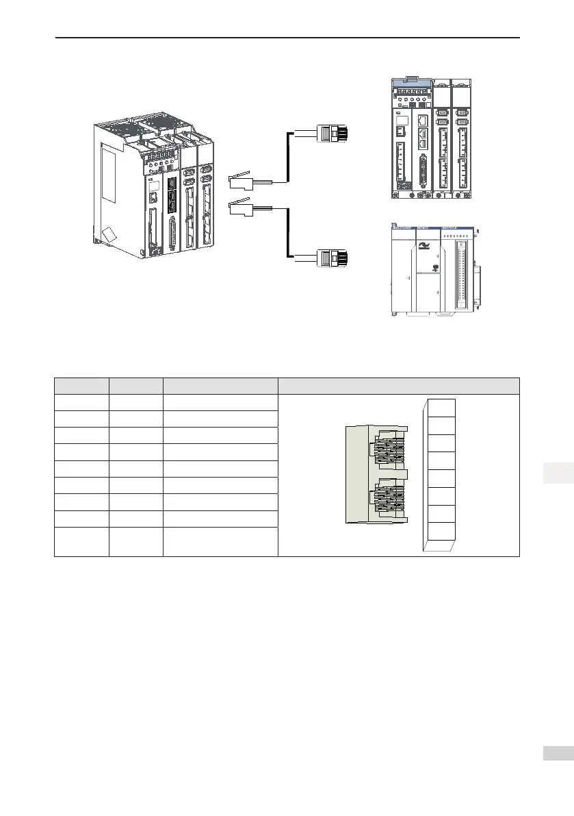
Figure 3-15 Communication wiring diagram
3940
2 1
CN
5
CN
3
Ether NET Ether CAT
CN1 RS48
5
C
N
2
C
A
N
CANERR
CANRUN
BF
SF
ER
R
RU
N
RU
N
/STOP
MF
K
0 1 2 3 7654
2 765410 3
4 5 6 73210
I
II
CN 4
EtherCAT
EtherCAT
Multi-device
communication
cables for the
servo drive
Servo drive and PLC
communication cables
ECAT_OUT
ECAT_IN
Communication signal connectors (CN4 and CN5) are EtherCAT interface connectors. The interface line from
the master station is connected to CN5 (IN), and CN4 (OUT) is connected to the next slave device.
Table 3-15 Pindenitionofcommunicationsignalterminalconnectors
Pin No. Signal Function Description Terminal Pin Layout
1 TX+ Datatransmit+
1
2
3
4
5
6
8
7
2 TX- Data transmit-
3 RX+ Datareceive+
4 - -
5 - -
6 RX- Data receive–
7 - -
8 - -
Housing PE Shield

 Loading...


