43
System components
Product Support: www.instron.com
5. Re-insert the voltage selector unit into the connector so that the required voltage
faces front.
6. If necessary, change the fuse holder. Refer to“Replace a Fuse” on page 102 for
instructions on replacing a fuse.
7. Re-install the fuse holder into the connector. Ensure that the indicator pin now indi-
cates the correct input voltage. See Figure 4 on page 41 for reference.
8. Reconnect the power cable to mains power and turn on the system. Verify that the
white
DISABLED indicator on the indicator panel illuminates.
9. Before you carry out any testing, perform the procedure described in “First time
startup” on page 51.
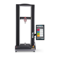
System components
Instron
®
Service installs your testing system. These diagrams and instructions are
provided as a reference if you need to move the system after the initial installation.
The Retrofit Controller houses all the components required to control the testing system,
taking over all control functions from the original load frame, including the power input
connector.
The Bluehill
®
Operator Dashboard is mounted on a bracket attached to the frame
column.
A new front cover is installed on the frame base which includes a new emergency stop
button and the indicator panel. A new handset is connected internally and mounted on
the frame column.
You operate the testing system via the Bluehill
®
Operator Dashboard and the handset.