39
Mount fixtures
Product Support: www.instron.com
3. Place the lumber between the adjustable crosshead and tension crosshead. Ensure that the tension
crosshead is securely supported and level. If the tension crosshead does not remain level during
adjustment, it can bind on the columns and become stuck.
4. Loosen the socket head cap screws that secure each retaining ring (1 and 4, Figure 9) (use hex key).
Remove the retaining rings from each column. If spacers (2) are present do not remove them; they
will simply slide along the column as the crosshead is moved, just make sure that they slide smoothly
over any notch.
5. Adjust the adjustable crosshead until the lower surface of the tension crosshead is above the desired
notch.
6. Reinstall the lower retaining rings according to the style of retaining rings used for your frame (see
Table 10 on page 39):
a. For frames that use the bolt-on style of lower retaining rings, place the lower retaining rings (4)
into the notches and start the socket head cap screws into the bottom of the tension crosshead.
Lower the tension crosshead so that it rests on the lower retaining rings. Tighten the socket head
cap screws until seated plus one-quarter turn.
b. For frames that use the hinged clam style or two-piece style of lower retaining rings, place the
lower retaining rings (4) into the notches and tighten the socket head cap screws until seated
plus one-quarter turn. Lower the tension crosshead so that it rests on the lower retaining rings.
Place the upper retaining rings (1) into the notches and tighten the socket head cap screws until
seated plus one-quarter turn.
7. Lower the adjustable crosshead and remove the lumber.
8. Normal operation can now resume.
For 600DX frame models, the upper retaining rings are not used when the tension crosshead is in the
highest notch position. The crosshead is secured in place by the column caps.
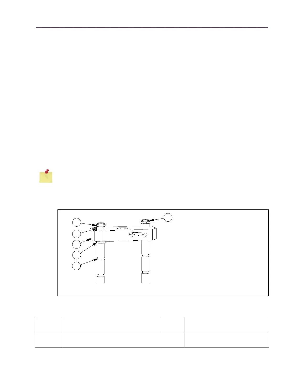
Figure 9. Tension crosshead and retaining rings.
1. Upper retaining ring
2. Spacer (not used on all models)
3. Tension crosshead
4. Lower retaining ring
5. Notch
6. Column cap or bolt
1
2
3
4
5
6
Table 10. Retaining ring use, style and fastener information.
Frame
Model Upper Retaining Ring Spacer Lower Retaining Ring
300DX-G1
Hinged clam style, one M8 SHCS
1
(use 6 mm hex key)
Yes
Hinged clam style, one M8 SHCS
(use 6 mm hex key)
 Loading...


